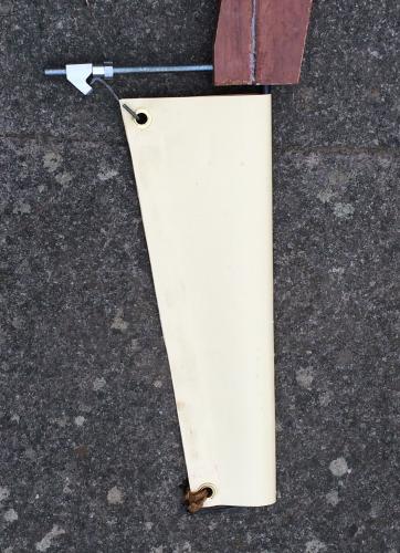
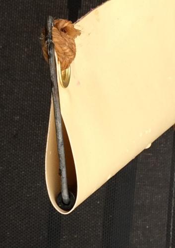
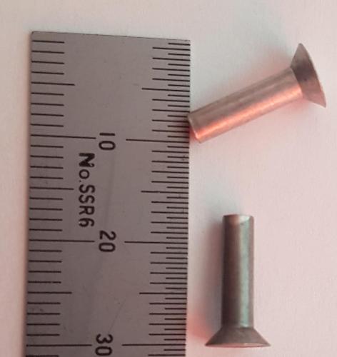
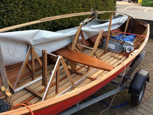
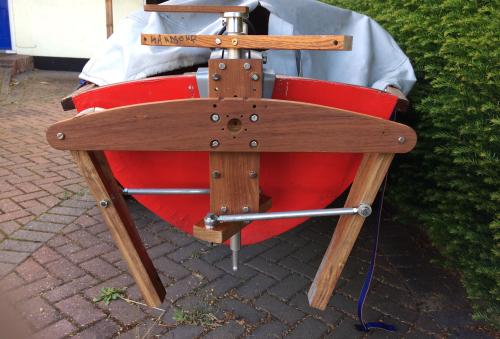
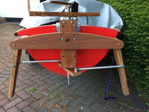
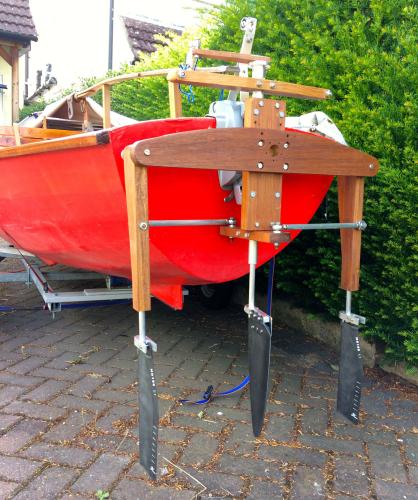
![]() |
If you want to see where you are going and leave your hands free you need some kind of pedal propulsion system; the Peduloh, famous throughout this forum, a Mirage Drive, or a contraption which involves pedals such as a pedal operated propeller. After much thought I've finally made a decision on a system and started building the Contrap-yuloh.
It will be a single oscillating fin with a horizontal pivot nearly at the top of the transom. The fin itself will be flexible so that the camber changes with each change of direction, and will have adjustable angle of attack. If you look at Youtube videos you notice that this type of device causes the back of the boat to wag in the opposite direction wasting energy. So this device will have another non-oscillating fin which should capture some of that wasted energy and convert it into thrust, and at the same time it will also form the rudder. ![]() Image above shows rudder tube and wood mounted to a transom clamp/tilt assembly. The rudder tube was once the prop tube from my first CCC entry, and before that it was an industrial broom handle! ![]() Above, curved piece of wood will have a pulley at each end carrying stout marine string from the pedals to the top of the fin lever. The fin lever will pivot on that 10mm steel rod seen in picture. |
![]() |
Looking forward to seeing this evolve! Tim.
|
![]() ![]() |
simplesimon |
![]() |
If you have two fins working in opposition then the wagging should reduce.
Simon |
![]() |
I've considered two fins to eliminate wagging, and two fishtail fins, and a surface piercing prop and many more.... The single fin and rudder/fin seems to be a bit less work, and much more compact. I even have Delrin, propellers and other parts ready for a toothed belt drive bike pedal outboard but that requires some machining which I can't do at home.
|
![]() |
![]() Oscillating arm to carry the fin. Oilon bushes, nylon pulleys and spacers made and I've not quite figured out the tensioning of the fin itself yet. ![]() Fin itself will be thick PVC/nylon fabric carried on a glass fibre thick wall tube about 14" long. |
![]() |
No pictures yet but I made the first fin from thick PVC on nylon fabric wrapped around a GRP tube spar. I'm waiting for glue to arrive so the trailing edge/leech was duct taped, and eyelets in the corners allow attachment in a way which is supposed to control camber, twist and tacking angle (which is not really the correct phrase) - and then I couldn't resist dipping it in a tank of water in the garden and waggling it about. It was very gratifying to feel the thrust and minimal drag, but the reality of separately adjusting these parameters for maximum efficiency is very difficult so I will probably have to simplify things, getting closer to a Mirage Drive blade.
Also thinking about pedals now. The original plan was to have pedals pivoted from a beam across the gunwales for a low foot position but measurement showed that there is not really enough room for my feet, and the beam would make moving around the boat cumbersome. So, I may have to go with the Hobie style pedals or something like two roller skates on runners. Rummaging around in the garage, I found a couple of small pulleys which seem to have reasonably low friction so I will probably ditch those huge pulleys that I spent hours making and have a more compact system, and I won't have to make fairleads to prevent the line from jumping off the big pulleys. |
![]() |
Black Swan PVC glue arrived so I glued up the trailing edge of the fin and the join strength seems to be acceptable. Unfortunately this glue did not attach polycarbonate sheet (which I was hoping to use to stiffen the trailing edge) to the PVC fabric. Pictures show the fin with its tacking/tensioning mechanism, and a piece of fence wire making a sort of gaff spar to maintain tension in the trailing edge. This will be replaced with a bit of stainless rod eventually.
![]() ![]() |
![]() |
If it helps Alan I could probably find some aluminium 'aircraft' rivits and post them to you. Perhaps a dozen or so of those might attach your PVC sheet to a polycarbonate sheet. But it depends on the thicknesses of your material, the longest rivits I have are about 12mm long and 3mm diameter, but you would loose a couple of mm after they are set. You say PVC fabric - I am guessing it is actually thin sheet? (this sounds like a good AYRS project! - see my recent posts here)
|
![]() |
John P, definitely an AYRS interest project and if it works I'll be happy to give you a full report. Very kind of you to offer rivets; I have some pop rivets here of a suitable length and will consider using them.
4mm polyester Marlow "string" just arrived, and I am now working on the foot pedal arrangement. If you can imagine a garden swing with two seats clamped to the floorboards, that's what it will look like. |
![]() |
![]() Alan - the rivits I have are as this picture if you would like a dozen or so. I have some shorter ones as well, but I have found it easy to cut the longer ones shorter with good wire cutters. I make the diameter of these rivits about 3.1mm. They might be better than pop rivits because they can be set flush on both sides of the material. I think these are fairly hard alloy, but for riviting plastics you probably need a soft alloy - I suspect you could soften these to some extent by heating and letting cool, at least that works with precipitation hardened 6082 alloy and suchlike. A full report - goody, goody! Even if your gadget doesn't work a report would be welcome - that would either warn others not to follow the same path, or even better it might encourage others to think "well, that old **** couldn't get it to work, but I bet I could!". Mind you, professional researchers don't often write reports to say that their experiments were a complete failure - they tend to write something like "results are not fully conclusive at this stage ...... there is a clear need for further funding to ........" Actually, I know of several AYRS members who are currently interested in waggly boat propulsion things, maybe we need of a more technical sounding name for them. Would be good if we could get a few of them together for one of our new-fangled Zoom meetings. Or another thought - it would be fun to have some comparative on-water trials (trying to avoid the word 'race') - I can think of one venue where we could set this up - we had a nice weekend at the Basingstoke Canal Centre last year which I wrote about in another thread here. And actually, it doesn't have to be all about speed, we have equipment that would measure thrust and for people who want auxiliary propulsion for larger vessels that's what matters. |
![]() |
I remember , as will people such as Graham, of an incredible AYRS meeting at Barton Turf where lots of 'researchers' were trialling their designs, going off in all directions. A fantastic meeting of very imaginative ideas.
Richard |
![]() |
I think you can see what's going on in this picture, showing progress so far. I'm making the backrest and pedal frame, and it uses the existing centre thwart. After the picture was taken I added some extra holes to allow some adjustment of the backrest and pedal frame. Several other parts made but I'm waiting on screws.
![]() |
![]() |
The pedal frame of this device (Contrap-yuloh Recreational Aquatic Propulsion) is about finished but I had so much trouble with creating the fins that I bought some Mirage Drive fins, rudder and "masts". I tried gluing, welding (the most common way to join PVC coated nylon fabric), and solid fins but wasn't happy with any of them or the time it would take to perfect welding of the fabric.
Also I went off my plan for a single flapping fin and mildly-flapping-boat-with-energy-recovery idea and sat around for a very considerable time pondering the next step. Is it just me or do others go through hopeless give-it-up stages with their pet projects? Anyway, I finally decided to take Simplesimon's obviously better idea and put in the work required to make two fins in opposition. Pictures below of progress to date: ![]() ![]() Edit: The rudder tube is now also the torque tube transferring torque from the yoke to the fin levers so the clamps for the rudder tube are mildly modified to be bearing blocks. The rudder shaft runs in PTFE bushes and there is very little friction which would cause the rudder to rotate with the tube. |
![]() |
That's looking impressive.
Can see the opposing bi and how that works, would be interested in seeng e pedal end and how that connects.
Can't see how the fins twsit/flex or whatever to translate the sideways motion into a forward moment.
Tim.
|
![]() |
Tim, I just assumed you were looking over my shoulder and could see what's happening! The fins are not yet fitted and extend from the bottom of the wooden bits. The bottom of the wooden bits are just above the waterline.
|
![]() |
Gotcha.
|
![]() |
Almost ready for testing now, here is a picture of the complete drive unit with its fins and rudder. I have shortened the wooden fin levers but it looks like they may reach just below the waterline so I may shorten them a bit more after testing. Small pulley at the top on an aluminium bracket is for an uphaul to tilt the device when beaching and launching.
![]() |
![]() |
I'm looking forward to seeing this working. It's an impressive piece of engineering. Do you reckon the power loss in the transmission will be minimal or in any way noticeable?
|
![]() |
Very little friction, I'm more concerned about the possibility of breaking parts of it. Just trying to get organised enough to test it on the water now.
|
![]() |
Get's more and more interesting! good luck with trials.
|
Free forum by Nabble | Edit this page |