A Duck Punt for the Cordless Canoe Challenge

123
123

|
Jeremy |
A Duck Punt for the Cordless Canoe Challenge
|
|
|
|
Timmo |
Re: Aero Mk 2 - just for the Cordless Canoe Challenge
|
|
|
|
Jeremy |
Re: Aero Mk 2 - just for the Cordless Canoe Challenge
|
|
|
|
Chris Waite |
Re: Aero Mk 2 - just for the Cordless Canoe Challenge
|
|
|
|
Jeremy |
Re: Aero Mk 2 - just for the Cordless Canoe Challenge
|
|
|
|
BrianP |
Re: Aero Mk 2 - just for the Cordless Canoe Challenge
|
|
|
|
Jeremy |
Re: Aero Mk 2 - just for the Cordless Canoe Challenge
|
|
|
|
Jeremy |
Re: Aero Mk 2 - just for the Cordless Canoe Challenge
|
|

|
|
Jeremy |
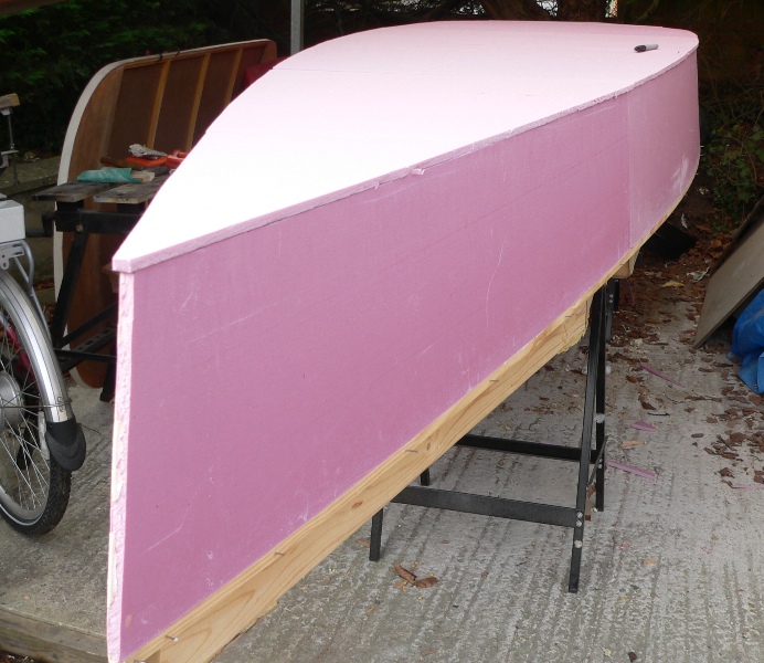
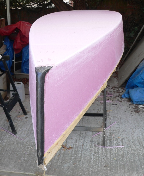
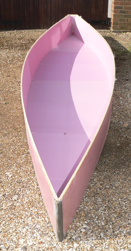
Duck Punt build
|
|
|
|
Jeremy |
Re: Duck Punt build
|
|
|
|
Jeremy |
Re: Duck Punt build
|
|
|
|
Jeremy |
Re: Duck Punt build
|
|
|
|
Jeremy |
Re: Duck Punt build
|
|
|
|
Randonneur |
Re: Duck Punt build
|
|

|
|
Jeremy |
Re: Duck Punt build
|
|
|
|
Jeremy |
Re: Duck Punt build
|
|
|
|
Jeremy |
Re: Duck Punt build
|
|
|
|
Jeremy |
Re: Duck Punt build
|
|
|
|
Alan |
Re: Duck Punt build
|
|
|
|
Jeremy |
Re: Duck Punt build
|
|
| Free forum by Nabble | Edit this page |