CNC Plywood cutting

1234
1234

|
|
After unpacking the pre-cut pieces of plywood as water-jet cut by Luffman Engineering at Tiverton, I made little progress with Josephine's row boat until a few days ago - house DIY and other interests seem to have taken over from boat building this past winter. However, a few days ago I cleared enough space in our garage to start fitting some of the plywood parts together - its still a 'flat pack' but now the sections of the hull panels are joined to make panels the full length of the boat - very flopitty at this stage.
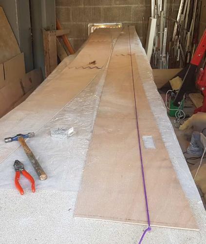 So far I am pleased with the way the parts are fitting together but the real test will come when I start assembling the main panels into a hull, maybe later this week. The finger style scarf joints seem to work well, see photo. Although the tapered overlap style of scarf joint is not all that difficult to make, these finger joints are even easier and I suspect equally strong so if you are using computer controlled cutting you might as well include them when you have the parts cut. I set up a long temporary work bench from some scrap pieces of chipboard then laid out the panels with a piece of polythene sheet under each joint, then wetted out a small piece of light glass cloth over each joint, covered the joints with more pieces of polythene then clamped flat blocks of wood on top to compress the whole sandwich. I know from a past experience that you need to use thick polythene for this, thin polythene wrinkles when it comes into contact with the epoxy. Actually, for the first panel I just used the weight of some bricks instead of clamps but the clamps worked better, or maybe I could have done with heavier bricks. I had the fingers cut with a small gap, I think it was 0.5mm (20 thou) for the epoxy to permeate, I dont know whether this is really necessary though. Still amazes me that a high pressure jet of water can cut with this accuracy. For each long panel I had small holes cut near each end of each sub panel, these holes lining up when the sub-panels are correctly positioned. This allowed the panels to be aligned on the bench by lining up these holes beneath a tight (purple) string (see photo below) - I would not rely on a tight string for vertical alignment since there must always be some sag in the string but its fine for horizontal alignment. 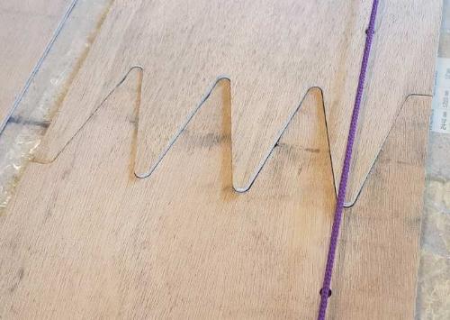 When we lived near St Albans our house was next door to some hospital buildings that the NHS no longer needed and when these buildings were demolished, needless to say to clear land for more housing, I noticed that rough shelving in a store building was made from approximately 18foot lengths of soft wood that was straight grained and totally free of knots. Also, when the hospital laboratory benches were demolished long lengths of teak something like 2 foot wide and more than an inch thick were discarded. I did manage to get hold of just a few pieces of this timber although most of it was carted away by a guy with a pickup truck who said that he needed it for his wood burning stove! Anyway, I have been storing this timber for years so the row boat seemed a good use for the softwood, hence I have been using a long straight cutter in my router bench to thickness it to the small sections needed for this suposedly light weight boat. Three long strips have been cut and epoxy glued onto the 3mm plywood panel what will be the floor of the boat so as to take the weight of a person. Two more long strips have been cut make what I think are called deck carlins - these support the inner edge of the side decks. Regarding the deck carlins, this afternoon I routered the initially 40 x 12 mm section into a channel section that should have almost the same stiffness vertically but be a bit lighter. Before routering each deck carlin weighed about 850gms, after it weighed about 600gms - well it all helps surely. In the same vein, Josephine has brought us some titanium cutlery with lightening holes in it - rather nice cutlery actually and not all that expensive. 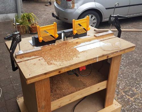 This picture shows my router table which also doubles as a general purpose workbench with a removable plywood top surface. The router parts were taken from a cheap but rather nasty ready made router table that I got from the internet - I still could do with making a new 'fence' since the one supplied, as in the photo, is only straight and vertical when I pack shims under it and in any case its too short for the bench. Just visible below the top of the bench is the handwheel that raises and lowers the router cutter, also the emergency stop button for the router motor. Note that the top of the bench is overhanging which is very handy for clamping items to it. Also, the bench has wheels at one end so that I can wheel it from my workshop (originally the dining room) out into the garden when I want to work on long items or when I want to make a lot of mess. Enough writing for now! |
|
|
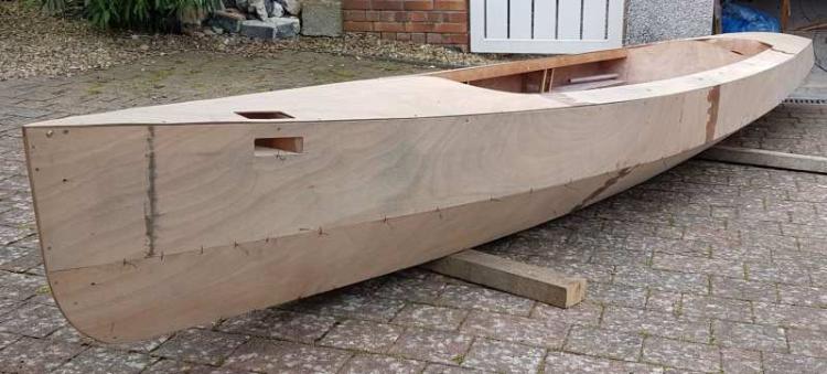 An update on progress on Josephine's rowing boat. The parts that I showed as a 'flat pack' in a previous post are now all dry assembled into a three dimensional form that I think somewhat resembles a boat. The finger joints between panels are epoxy glued but otherwise there are only copper wire ties plus a few temporary woodscrews holding it together at this stage. The assembly of the hull to this point has not actually taken many hours, although it has been spread out over several months. I have found it a satisfying process, seeing the shape of the boat develop from the flat panels. It is perhaps the most enjoyable part of boat building, so I have been feeling no desire to rush it which is perhaps why it has taken a while. The assembly was done without any jig or 'strong back', relying entirely on the shapes of the panels to produce the shape of the boat. The other day we took the boat outside to weigh it in its current form and took a pic or two - see above. We weighed it with rather rickety old bathroom scales, modern electronic scales could be more accurate. It was hard to balance such a long object (15 foot LOA) on the scales, and we had to raise the boat off the scales on blocks so as to read the dial with a small mirror. As best I can tell the hull weighs about 23kg. This is with pretty well all the plywood given one generous epoxy coat on the internal surfaces but without any glass reinforcement or epoxy fillets at the joints between plywood panels, also without the external sheathing of light glass cloth and epoxy and without any of the metal fittings or the paint. The predicted final weight of the boat is 40kgs, this includes the oars and other removable parts such as seats, seat cushions, the folding outriggers etc. I guess that at this stage I am probably about on target to achieve that final weight, will be interesting to see and useful information if I ever make any more boats. (where would I put them though!). One question, when pre-coating the plywood prior to assembly I left a strip of bare plywood along the edges which are later going to be joined with strips of biaxial glass and/or epoxy fillets. My thinking at the time was that the glass/epoxy would be best applied to bare wood than to previous epoxy that has already fully hardened. Does this make sense ? - Perhaps it makes no odds really. Once this boat is finished I will probably place the .dxf files for the parts somewhere on the internet so that if anyone fancies making a copy they can find themselves a cutting firm to make a kit, or load the files into a free dxf viewer then cut the parts out manually. However, I won't do that until we have the boat on the water and checked for any problems. I wouldn't want to be responsible for lots of boats that all float the wrong way up! I don't think I will do any more boat building this summer since we plan to go away sailing abroad very soon,indeed by our original plan we should already be sailing on the Baltic Sea. Maybe we will get to Cobnor later on, not sure though. |
|
|
Hi John.
Your boat is looking good, I'm sure she'll work really well. In theory a wet glue bond will always be stronger than a dry one as it forms a chemical bond rather than a mechanical one. I'm not sure it makes that much difference in practice although you should give cured epoxy a good sand if applying another coat on top. The other question is whether to fillet, tape or both, and in what order. Pete Martin is still paddling around in my old Polythene Pam and she has no tape at all but she does have acute angles at the chines to run a good deep fillet into. Where the chines flatten out as towards your bow and similarly on Katie Beardie some tape is required as the angle is too shallow to take much of a fillet. My answer on Katie was to prime the ply with neat epoxy then run a fillet while it is still tacky. I then taped over the fillet. Belt, Braces and a bit of Bailer Twine. |
|
|
This post was updated on .
I concur with my honourable friend. Tape is a tad overrated I think. It's very easy for the tape to absorb a lot of the epoxy and leave the wood a little dry of epoxy.
I surprised myself with how easy it was to pull epoxied tape from Illusion's panels. Even the hull bottom glassfibre was removed fairly easy with a flexible 3in wide blade and a good tug. The weakness is the very first joint between the wood and the first layer of tape. That in turn depends on the strength of the glue holding the outer veneer - paper thin on cheap and cheerful ply from Asia. My advice is to flood the wood with epoxy and leave it for an hour or two to soak through. It should still be at its chemical bond stage e.g. slightly tacky. At this point add even more epoxy to the wood, wait again for it to soak in, or maybe not. Repeat extra coats until no more soaks in. Finally add the tape. Make some test joints with scrap, then pull or cut them apart. You might be surprised. cheers Paul |
|
|
This post was updated on .
Paul says that he found it quite easy to pull epoxied tape away from from plywood. He then says that the weakness depends on the strength of the glue holding the outer layer of the plywood. This suggests that when he was pulling away the tape he was actually breaking the bond between the outer layer of plywood and the layer underneath - is that so? If that is the case then the weakness is within the plywood, and the bond between between the wood and the epoxy is not the 'weak link'.
I would say that when I have seen wood-epoxy joints break, generally some wood fibres have pulled away with the epoxy, rather than the epoxy pulling away from the surface of the wood. This suggests that the structure is actually as strong as it can be with glue alone, given that wood has little strength in the cross grain direction. Intuitively I agree that it seems likely to be a good idea to flood the wood with epoxy and allow it to penetrate before adding more layers, not that I have seen any tests to prove that, perhaps West have published the results of relevant tests in their 'Epoxyworks' articles. I am using the 'Epafd' resin from Reactive Resins Ltd. This is a low viscosity resin (viscosity given as 650 to 750 Mpa.s at 25 degrees) so I hope it will penetrate well into the wood. Its an interesting question as to just how epoxy fillet/tape joints are best made between plywood panels - that could be an interesting project for a student thesis - perhaps I should suggest it to my lecturer friend at the Marine Dept in Plymouth Uni. When we were at Semaine do Golfe last year they had a demonstration of stitch and glue boatbuilding on the quayside at Vannes, so I think I will basically follow the method they demonstrated. Starting from the point at which the plywood panels are stitched together - with cable ties in the demonstration although I have used the more traditional copper wire - the joints are first painted with neat resin. Strips of fibreglass are cut from a sheet of stitched biaxial glass fibre material - they did not use ready made tape. Once the resin is partly set (I am not quite sure how to judge that) the strips of glass fibre are pressed down onto the resin and the tackyness of the resin holds the glass in place. Most of the glass remains dry of resin at this stage. Later on more resin is worked into the glass to complete the joint. I think the use of strips of biaxial material makes sense, since it means that all the glass fibres span the joint, if ready made woven tape is used only half the fibres cross the joint. Also I have found that with woven tape you tend to end up with a ridge along each edge of the tape, requiring more sanding for a neat look. I have brought a piece of biaxial glass fibre, 320gm/m2 weight, and cut a few trial strips about 40mm wide. I am not sure just what width is best, but I dont think it needs to be all that wide given that this is a joint between plywood panels only 3mm thick. It helps to use sharp scissors, but not Josephine's scissors. All the fibres are at 45 degrees to the length of the strips and lines of stitching in the material provide a good guide for cutting straight. Once the strips have been cut they do tend to fall apart, so need to be handled with care. I wonder whether to just apply the glass straight to the epoxy coated wood, as in the demonstration I saw in France, or whether to do as Graham suggests and run a fillet of epoxy 'bog' - (lightweight fairing compound, or epoxy/micro balloon mixture) between the wood and the glass fibre. Adding just a little such filler along the join would increase the total thickness of the joint, stiffening it against bending and would also help smooth over the wire stitches I have tied, so I may well do that. If I do use such a fillet I think I would only do so where there is a reasonable angle between the panels, make the fillet quite small, so that the fillet just rounds off the sharp internal corner a bit and most of the width of the glass is laid over wood, not over the fillet material. Does that make sense? All this probably needs to wait awhile, we want to go sailing while the weather is sunny. |
|
|
Hi John. I am finding it interesting reading about this, as I finished building my little dinghy over 30 years ago now (using West Epoxy). It is bringing back some interesting memories.
I also used copper ties, but following the instructions in the magazine article I was reading, I glued the edges in between the ties with epoxy thickened with wood fibres (microfibres) to a toothpaste consistency. Once these two inch strips had set, they were strong enough to hold the ply together after the copper ties were snipped and removed. No metal was left in the joint. I then finished the seam fillet with more thickened epoxy in the gaps left and in the wire holes, prior to moving on to the taping of the seams. Yes, the ridge along the edge of woven tape is very annoying and difficult to get rid of. I still shows in places on my dinghy, despite years of sanding and repainting. I don't think that leaving the epoxy to soak in for a while, or start to set, is necessary at all. I certainly didn't on mine all those years ago. Applying epoxy first in sufficient quantity to soak into the wood, is all that is required, and then the tape (or strips of biaxial) can be laid directly onto the wet surface and more epoxy applied immediately to soak through the fibres and change them from white to transparent. I doubt the dry tape would pull epoxy out of the wood at that point. I do think that it is an advantage to put wet-on-wet, to maintain a structural connection rather than relying on an adhesive bond. I used brushes that were home made out of small rope ends bound with insulating tape, which can then be thrown away. Make a good supply before you start. A dabbing action should force the epoxy mix into the fibres, but a soft rope brush is required to avoid them pulling fibres out of the fabric. Change the brush as soon as it starts setting or the stiffening brush will have the same effect. I have heard of others using rollers made out of alternate size washers on a bolt, but I have never tried that, and they would need to be cleaned frequently. I do remember that mixing small batches is key - or you either get smoke and flames or the mix goes off before you can use it. Good luck with the build, and please keep up your progress reports. You don't know how much vicarious pleasure you are giving to your readers! Ian |
|
|
In reply to this post by John P
Hi John
Enjoying watching the boat come together. While not necessarily correct or best my approach on a stitch and tape canoe was pretty much as you saw in France with the addition of the fillets. I have learned to run masking tape along the outside of the joint between the wire ties before starting. Saves lots of drips and encourages resin to hang around and soak into end grain. If you then tape over the holes after pulling the ties they'll fill nicely as you fillet. First doused the joint in epoxy. Then I 'tack filleted' between the wire ties to rigidiify the structure so I could cut and pull the ties (I know they could stay there, but it feels untidy somehow.) Then I filleted properly covering the tacking fillets completely. I taped each fillet as it was gong off and still slightly soft. Easier to smooth them by running the back of an old spoon over the tape as you apply it than to sand the fillets when they're hard. Finished by adding unthickened resin to thoroughly wet out the glass. I did use glass tape but sanding the edges off was indeed a pain. Cutting biaxial cloth makes sense. That was all in one day, the first fillets were hard enough for the wire ties to come out in a couple of hours (standard West hardener) and moving on before anything cured completely ensured there was a good chemical bond between all the epoxy layers. Can just do one seam at a time for the same result in shorter packages of time. I think the fillet adds a lot of strength. A single layer of glassfibre, even when rigidified with epoxy, does not significantly resist bending. So while it will hold the planks together it can't stop a joint from flexing. Some joints will be rigidified by the curve of the two planks meeting. Others will benefit from assistance. It's easy to do when you're building, ten times harder to do as a retro fix later, so I think they're worth the effort. But I have no science to back me so I'm open to all corrections and better suggestions. Tim.
|
|
|
Just to be super pedantic, don't use fairing compound for a fillet, use filleting compound. I've found it fairly easy to feather the edge of tape. If you wait until the epoxy has got to the sticky toffee stage you can rip off the outside thread from the tape which causes the ridge. Then smooth it all off with fairing compound.
|
|
|
In reply to this post by John P
John,
I think the weakness I saw was partly cheap ply and partly lack of epoxy in the wood. I must have worked too fast, the epoxy was too thick, temperature too cold etc. One can be deceived - the glass can go clear because it has absorbed all the epoxy. So next time will I flood the area with thin epoxy, between tape as Tim suggested, and make a coffee and read the DCA Solent rambles.  Paul Fisher says some people prefer to epoxy the wood and let it dry. Next day they add tape/cloth. cheers Paul |
|
|
Thanks, there are some useful comments here. There seems to be general agreement that it is best to start by brushing the joint with sufficient neat epoxy, that makes sense I think. Timmo's tip to run masking tape on the outside of the joint to prevent the epoxy running through sounds fine, but I have put rather a lot of wire ties, probably more than I needed to, so if I use masking tape I will have to use lots of short lengths and its not going to stop resin getting through the holes I used for the wire ties. I may give it a try though.
After the initial epoxy coating the question is whether or not to run an epoxy fillet using some kind of epoxy filleting material. I can see that a fillet could strengthen the joint against bending, although the demonstration I saw in France skipped the filleting stage. I realise now that what is sold as fairing compound is probably not be the right material for fillets. I had not heard of filleting compound until Graham mentioned it, I now see that West sell the filler powder to mix with epoxy to make filletts, so that must be filleting compound. I wonder what is in this filler powder, if it is colloidal silica I have some of that. Maybe a mix of colloidal silica and microballoons would do? Next comes the glass and more epoxy, unless you believe that the fillet alone is good enough. For some of the internal 'furniture' I suspect that the fillet alone is good enough but I feel that I should lay glass over the joints between the main hull panels. I am pretty sure that a strip cut from biaxial cloth will be better than woven tape since, as I said before, all the fibres cross the joint. Still, if tape were used, Graham's tip to rip off the outer 'selvage' before the epoxy is fully hardened does make sense. |
|
|
The filleting powder is usually something with fibres in, to give it a lot more strength than the fillers and stiffeners. The West stuff is cotton fibre, IIRC, and other suppliers sell versions with glass fibres. I've always used the West stuff, as is seems to work well, although it doesn't seem to flow and shape as well as some other, less strong, filleting materials
|
|
|
In reply to this post by John P
Your new rowing hull looks lovely John
I was trying to find the lines that I am sure you uploaded in the past, but can't. Any chance you could put them up again, here? Anyway, the obvious question is - Has anybody had a failure of an epoxy seam under less than brutal circumstances and if so, what did it consist of - fillet, glass fibre, etc? I use tape which may not be as strong as biaxial, but doesn't unravel while you're trying to install it; I refer back to my first question. I also recognize the other comments - 1. I tend to give the joint a lick of epoxy and do not stop to differentiate between 'wet', 'tacky' and 'off' though I usually go straight in and fillet in between the stitches where there is sufficient angle. Where there isn't, I use biaxial square tabs of tape in a diamond pattern to hold the seam while I remove the stitches entirely - 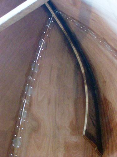 In fact, I’m a tad crazy, (just a tad?) – I strip the insulation off old electric cable to get the copper wire, then remove it anyway. In future I’m going for that green plastic-coated steel garden wire on the grounds that is cheap, strong and if it goes rusty, it won’t matter much, as it will have long since ended up in the bin, not the hull. 2. I am trying to remember, but I think I eventually kept any unruly edges properly opposed by using figure of eight stitches, or inserting an extra (copper) tie through the seam round the inner and outer aspect of each stitch to proximate them. Or in extremis, with an (appropriately bent to suit any slight angle) 'penny' washer under the head of a screw through the seam and into a rectangular plastic kitchen cabinet block - 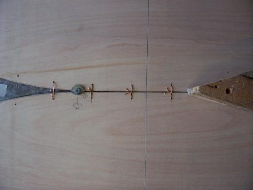 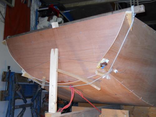 The washer, screw and block are beyond the interest of epoxy, so are easily removed once cured-epoxy alignment has been achieved. 3. I next fill in the fillet in the stitch spaces and when cured, tape to taste – inside. Then the same outside after filler to obliterate any holes, gaps and cracks, as I am not so phisticated as to CNC and there are occasional imperfections. Glory be 4. Finally the seams, are epoxy sheathed with Tesco’s finest poly-cotton, as is the rest of the hull  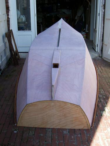 ....before receiving a couple of (top) coats of Jotun two part polyurethane; no primer, no undercoat, no problem. At least not in the past couple of decades. I like the idea of masking tape outside to catch any drips and encourage them to get involved with the seam. As for the selvage, I use a small Surform - 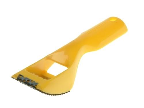 Once the epoxy is hard, this little piece of kit rips that raised edge down to a fine, if fuzzy, taper that can then be included in the general mayhem. It's not as if a selvage is doing much out there an inch or so from the seam itself. In fact the baby Surform is my favourite tool Small, but seriously aggressive Bodge on Boogaloo CW |
|
|
In reply to this post by Jeremy
Here's a link to the UK Epoxy page on Fillers etc.
It appears I was slightly wrong, ( That's a bit like being slightly pregnant,) the fairing filler can be used for filleting on lightweight boats. Anyhoo read for yourselves. http://www.epoxy-resins.co.uk/Products.htm#Top Graham. |
|
|
In reply to this post by Chris Waite
Couplle of comments
a) I've always used thinned epoxy for the first coat in the hope that it soaks in better. b) Colloidal silica is a thickening powder, it doesn't give any extra strength, just viscosity. Neither do microballoons increase strength. I used cellulose fibres (denatured cotton I think they are) either West or SP. c) (For CW) Steel garden wire takes nicks out of the edge of tools if you inadventently plane it etc. (Been there, done that!) Copper wire just gets cut. d) I obviously have forgotten how to count to a "couple"! Cheers Simon |
|
|
In reply to this post by John P
After a break of about 9 months I have now restarted work on Josephine's rowboat. It still looks very much the same as in the picture I posted back in June last year, but the seams between the plywood hull panels are all now sealed up and there is more structure inside. Maybe it will be ready for the Thames row this year.
I thought you might be interested to see some drag predictions for the boat that I produced using the Michlet software: (download at http://www.boatdesign.net/forums/attachments/design-software/98927d1427290658-michlet-9-33-released-mlt933.zip)  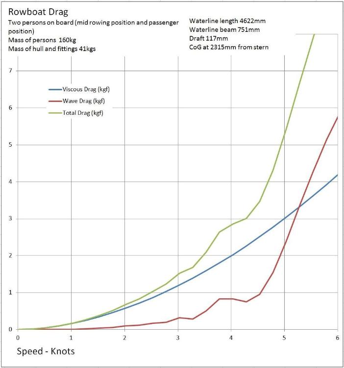 This rowboat is designed to be used either by a rower on their own or a rower with a single passenger. Since it is a fairly short boat this requires two rowing positions to keep the pitch trim of the boat reasonable when the passenger is added to the load. The boat has a transom stern and the two rowing positions are located so that the transom is just clear of the water with either one or two persons on board, this requires that the boat trims rather more bow down with two on board than with just one. The charts above indicate that, as would be expected, there will be more drag with two persons on board than with one on board, but not nearly twice as much. At the speeds that are likely to be attained most of the drag is viscous drag, i.e. skin friction, although wave making drag does start to rise quite rapidly above about 4.3 knots. (Profile drag is small, I understand that Michlet includes this in the skin friction results) I am not sure what thrust is realistically achievable from a pair of oars operated by a typical pensioner. The lever arm of the oars means that the thrust at the blade is only about a third of that at the handle, and this thrust is only applied over about half of the rowing cycle. So, to get a time averaged thrust of, say, 3kgf would require something in the region of 18kgf applied to the oars, is this a reasonable guess at the maximum thrust feasible over the time it takes to row between locks or pub stops? If so, the maximum speed of the boat should be about 4.7knots with one person on board rowing and about 4.3 knots with a passenger. A bit less again with a full load of camping equipment, the foldaway launch trolley and a Brompton folding bicycle. I am hoping that once the boat is finished it will be possible to find out how accurate are the Michlet predictions. If we can borow a motorboat it should be possible to tow the boat at various speeds and record the tension in the tow line. An acurate speed measurement is possible with any mobile phone these days and I see that you can buy a digital balance for weighing hand luggage taken on a flight, that should have the right sort of load range. Reasonably long but light tow line needed so that the towed boat is not in propeller wash. |
|
|
That is interesting, thanks for the data.
Just a mention from my own experience. I sail a very small 7' 11" dinghy which has two rowing positions for the exact same reason. However, I only carry one set of oars and rowlocks. With a passenger (or even two if lightweight) sat in the stern, I sit further forward and find that the oars are no longer a suitable length, giving a different and more awkward feel to the rowing. Basically, the beam is slightly narrower and the gunwale higher. I am sure this has more effect on my rowing efficiency than the change in drag, although there is a noticeable change in drag. Also, the knees of the passenger get in the way of the stroke, which doesn't help their comfort as they have to adopt a strange sitting posture. Ian |
|
|
Ian - It sounds as though you need to build a longer boat.
Mind you, if you are building a row boat to carry a passenger there could be a reason to make the seating for the passenger not too comfortable - could make the passenger more wlling to take a turn at the oars from time to time. John |
|
|
I have been making a simple launching trolley for Josephines rowing boat, basically a cradle that fits under the boat amidships and is fitted with standard plastic launch trolley wheels with pneumatic tyres. It is tied in place with cords to cleats on the boat. An attachment at the bow of the boat should then allow the boat to be towed by a bicycle. I fitted the launching trolley wheels with delrin bushes that run on a 12mm diameter axle, the thought was that should have a bit less friction than the usual launch trolley axle diameter which I think is 1".
I had just done all that when I had the thought that I might do better to get wheel chair wheels that attach directly to the side of the boat. That is not a new idea, I saw a canoe like that at Beale Park, but what I hadnt realised until more recently is that wheel chair wheels can be made very easily detachable from a wheelchair. You can get a 'stub axle' with a button on the outboard end and you just need to press the button to release the wheel from the wheelchair. It does sound a nice idea to have wheels like that on the boat. The stub axles could fit into tubes sealed into the the sides of boat with glass fibre and epoxy. I think I will give that a try, will soon find out which type of wheels work best. The wheel chair wheels will probably be best for longer distances on smooth ground whereas the plastic wheels may well be more suitable for rough ground and beaches, also they will be imune to corrosion, unlike the wheelchair wheels. Unfortunately I will not be able to fit the top on the bouyancy tanks in the sides of the boat until the wheels arrive and the tubes for the axles are fitted, that will be a bit of a delay to the program which is otherwise going quite well now - almost ready to fit the deck then the outside can be sheathed and painted. |
|
|
This post was updated on .
Well, the wheelchair wheels for Josephine's boat have arrived, promptly delivered from a small charity that mends peoples 'mobility aids', somewhere 'up north' in Lancashire. (a boat is a 'mobility aid', - so that could be a name for a boat that can be fitted with wheelchair wheels but Josephine may already have a corny pun in mind for a name) The wheels are second hand but will be fine, after all they are probably going to be roughly used on tow paths and beaches. However, the bearings in the wheels are 12mm ID and the axles that I have ordered are 1/2" - from what I had read on the internet I had the impression that 1/2" was standard for all wheelchair axles but apparently not. I dont think I can just turn down the 1/2" axles because of the way little balls fit into the ends of them to locate them in the wheel chair, or in this case the boat. So the axles will have to be sent back and new ones ordered, then I can turn the tubes that will fit into the sides of the boat for the axles to plug into. And so it goes on. But progress is being made and it is more fun than the last DIY project which was bathroom renovation.
|
|
|
John,
I suggest you order a length of stainless 12mm rod on Ebay - it won't be expensive. If it runs full width under the boat, drill holes in the ends for split pins. Alternatively get one metre of 12mm threaded rod from Screwfix/Toolstation and use locking nuts, if the wheel bearings will run ok on the threads. I have about 48 locking nuts spare, after using just 2 on MilliBee! You are welcome to a pair in a jiffy bag. -Paul |
«
Return to Builds in Progress
|
1 view|%1 views
| Free forum by Nabble | Edit this page |