CNC Plywood cutting

1234
1234

|
|
Paul 12mm studding has an OD of 12mm but a minor diameter of 10.2 mm so in effect yoou are relying on 10mm rod NOT 12mm.
Richard |
|
|
Richard,
Point taken. But at 40kg hull weight even a 10mm axle is sufficient. And further strengthened by being clamped to a wooden cross member, plus pipe insulation, creating a useful launching trolley. Cheers Paul |
|
|
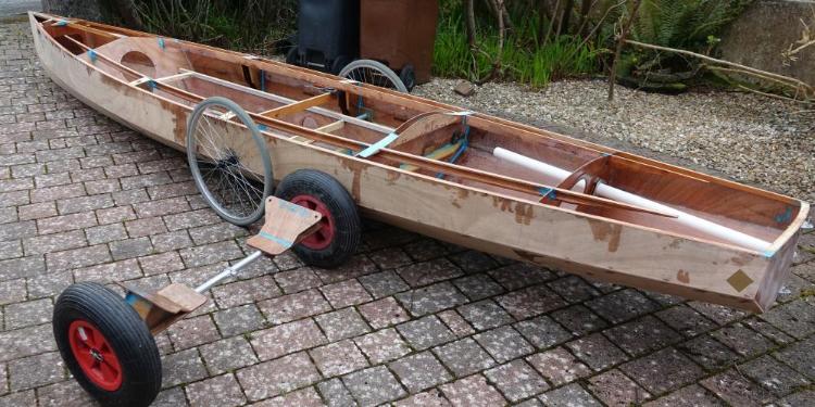 Thank you for the helpful suggestions re the launching trolley, but as the photo above we now have two options for launching trolleys for Josephine's row boat. The helpful people who sent me the wheelchair wheels have now provided axles to fit them. I have sent back the oversize axles that came from somewhere else and I have been able to turn tubular aluminium parts that fit into the boat to support the axles. I took the above photo about 12 hours after gluing these aluminium parts into the boat with thickened epoxy and a few minutes after taking the photo I was somewhat dismayed to see one of the wheels slump over sideways. I had not allowed nearly time enough for the epoxy to harden - It was a fairly cool night and I used slow hardener whereas I have mostly been using the fast hardener for this project. The epoxy was now starting to set so something had to be done quickly, so I got the parts clamped back together but without adding any new epoxy. I hope it will stick ok, but next time I have epoxy mixed I will overlay the joint with more epoxy and fibreglass to be sure. If this boat is really going to be towed by a bicycle the wheels and axles will need to stand up to bouncing over potholes. I would say that the wheel chair wheels do look a bit flimsy to support such a large object, but presumably they are suitable to support a heavy person which is much more weight than the boat. I am hoping the ground clearance with the wheelchair wheels will be enough for tarmac but the other trolley with the plastic wheels and fat tyres may be needed for rough towpaths and rocky beaches. I made the launching trolley with plastic wheels before deciding to try the wheelchair wheels. The plywood parts for that launch trolley were water-jet cut along with all the other plywood for the boat. The axle is an approximately 25mm OD x 16g 6082T6 aluminium tube with a sleeve joint in the middle so that it fits into the luggage space at the stern of the boat. Thinking about whether M12 studding would be strong enough for a launch trolley, I would point out that because of the way the plywood supports fit the hull of the boat the aluminium tube axle is actually loaded only in tension, not in bending. It did occur to me that with this design the 'axle' could be nothing more than a piece of string linking the two plywood parts but I preferred the aluminium tube since I think it would be tricky to get a trolley with just a string for an axle set in place under the boat. I would say that the wheel chair wheels are very easy to fit to the boat, just lift one side of the boat and plug in the wheel and axle. Then to release, push in a button in the end of the axle and pull off the wheel. The turquoise blue spots in the photo are Reactive Resins epoxy filler. I have found this nice stuff to use - more convenient and more consistent gloopyness than mixing my own filler with resin and filler powders. Mind you, the bright blue color would be no good if you want a clear varnish finish. I would say that the photo gives rather a false impression of the shape of the boat - wide angle lens effect. The freeboard is actually quite a lot higher at the bow than the stern, but looks the other way round in the photo. |
|
|
John,
Can I ask for a table of offsets for the boat? The Hulls program allows for 5 frames including bow and transom to define the shape/length (that's 3 bulkheads within the boat). Planking is automatic. She looks good at 16 feet, but a bit wider might allow sleeping aboard. cheers Paul |
|
|
Hi Paul - yes I can do a table of offsets, but not instantly since I dont have one at the moment. The boat was designed as a solid model then .dxf files for each piece of plywood were taken from this model using available software functions so there was no need to produce a traditional table of offsets. Is the Hulls program the one produced by Greg Carlson years quite a while back now?
The boat is about 15 feet long, not 16 feet. With minor alteration there could be space for one person to sleep on board without changing the beam. But there would not be room for two persons to sleep on board without increasing the beam significantly which would result in a boat not a lot different to our sailing dinghy, so there did not seem much point in doing that. Sleeping two persons end to end in a 15 foot boat could be one way, but I think that would compromise the internal arrangment for daytime use. I wanted to keep the large bouyancy compartments at the ends of the boat for possible coastal use. Since we gave up the idea of sleeping on board this boat I have strengthened the floor of the boat with a couple of transverse members and with the boat as it now is these transverse members would make it very uncomfortable for even one person to lie in the bottom of the boat even though there is the length and width available to do so. |
|
|
John,
I've just realised the PDF of the nested panels, that you uploaded, is a good enough start. I can reverse engineer approximate offsets from the bulkhead and transom sizes. Assuming the length of the A4 printed area is 2400mm I scale that to approx 210mm (the length of an A4 sheet, minus borders) Here is a Hulls model of 20ft row boat with a hull speed of 5.8kt, allegedly 
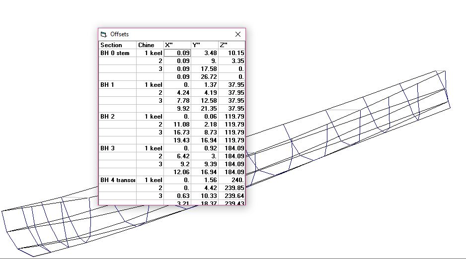 The table of offsets defines the entire hull. There is nothing else the user can change in CAD model, but simplicity is the key feature of Hulls. cheers Paul |
|
|
Hi Paul - I dont mind at all if you want to 'reverse engineer' Josephine's row boat, but I cant help wondering why you would want to do that. If you are thinking of making a similar boat you are welcome to any information but I would sugest that it would be sensible to wait until the boat is in the water and has been found to float the right way up! Working backwards from the image I posted of a dxf file sounds like a tedious way to go and in any case the shapes of the bulkheads are not what you would expect in a table of offsets since the bulkheads are sloped, i.e. they are not perpendicular to the water surface.
I think 'hull speed' in knots is conventionally considered to be 1.34*sqrt(waterline_line_length_in_feet) I am sure someone will correct me if that is not so. Presumably the odd units are because naval architecture is one of the older areas of technology. From this a 'hull speed' of 5.8 knots is about right for a 20 foot boat, given that the waterline length is a bit shorter than the overal length. Josephine's boat will have a lower hull speed simply because it is shorter. But 'hull speed' is not a 'speed limit' - more thrust always means more speed. I think the hull speed idea is just to give a rough indication of how fast a displacement style boat might go with moderate application of thrust. Also, the hull speed concept is based on wave making drag, so its less relevant to slim hulled boats such as we are considering. I wanted to keep the length of Josephines boat down to about 15 feet for a number of reasons: - Keeping the weight down for handling on shore = although a somewhat longer boat would be faster under oars, other things being equal it would be heavier. - length of our garage where it is being built - Not to look too huge on a car roof rack - Not to take up too much space stored under a cover in the garden - Possibity of towing on wheels behind a bicycle Regarding the last of these, I have been wheeling the unfinished boat around in our front garden and thinking about a tow bar to connect to the bicycle. I dont know what the law says about the size of trailer you can have behind a bicycle, perhaps it is the same as for a car. But I can imagine that the sight of this boat attached behind a Brompton folding bike is going to turn heads and get policement wondering if they should do something about it. I dont think I would be happy to cycle it though a town, but perhaps we might get away with it on the quiet lane down through our village to the beach. |
|
|
The boat is looking really good, John.
You are completely right when you say that hull speed is not a limit but marks the point at which the effort required to push the boat along increases substantially. But the problem with rowing boats is that the human body can only produce a tiny amount of power so exceeding the hull speed is very difficult. Added to that, human beings can't keep the power up for long - after a very short period the body runs out of oxygen and has to go into aerobic mode where the power output is matched to the oxygen input. It is the difference between sprint and long distance. And the reason you experience a second wind. The upshot is that any hull can be pushed along at its hull speed all day* but any attempt to exceed that will result in the rower giving up and stopping for a breather, a drink and a sausage sandwich at increasingly close intervals. For these reasons, sliding seat rowing boats are used only for racing over relatively short distances (usually 2km). Over longer distances, fixed seat boats are very competitive. *Those who follow the DCA's openboat group may have read my recent definition of 'all day' as 'three hours in the morning, three hours in the afternoon" but I have now reconsidered. My new definition of 'all day' is 'until you get bored'. |
|
|
In reply to this post by John P
John, I like to build a quick paper/card model to visualise a design. It's amazing what you can do with some super glue and laser printed A4 plans: 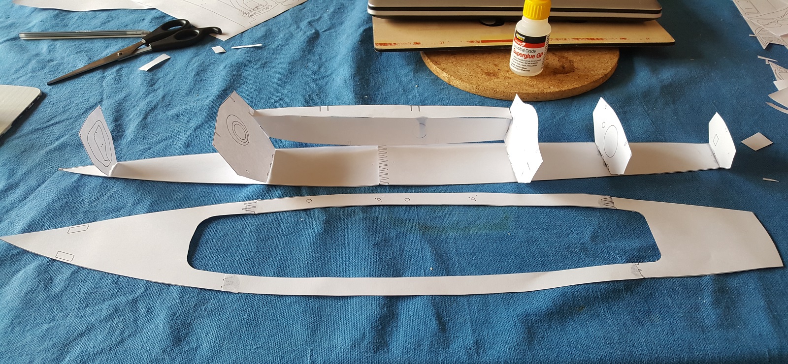 And yes I'm interested in a relatively efficient light hull, for electric drive, rowing and a small triangular sail for those mythical downwind moments. I do like the way the parts fit together with tabs and slots. Assembly is easy and accurate - in fact I built the starboard buoyancy chamber using tabs and slots in the paper. A touch of super glue locks them in place, and all the angles sort themselves out. The decking gives her very nice curves, something the pictures don't show fully perhaps. I see you have opted for Paradox style rudder control, from within the aft chamber. For buoyancy in the briny I would want to seal that chamber - a following sea could quickly fill it up. Well done for such a detailed, curvy design. cheers Paul |
|
|
Paul
I am impressed, indeed astonished, by how much you have done on this in such a short time, based presumably on just a small image I posted on this forum quite some time ago now. I would say that my cutting out file for the boat went through about three iterations and I am not sure that the one in the image on this thread is actually the one used to make the boat, although the differences might not show up in a small scale model. I did make a couple of mistakes with the final cutting file. I think what must have happened is that I had different versions of the design in different folders on my computer and I must have accidentally included a couple of the parts from a folder containing an earlier design iteration. This did cause a problem when I came to assemble the boat since I realised that something was wrong but it took me some time to work out which parts were the cause of the problem, then to make alterations by hand. Another mistake was to put tabs and slots for the tops of the bouyancy tanks in positions that would not allow final assembly of the top panels after finishing the epoxy coating of the tank insides - that was really silly since I knew that these panels would need to slide into place in an athwartships direction, so whyever did I put the tabs sticking out longitudinally! I can say that appart from where I made mistakes with the computer, the panels did all fit together remarkably accurately. Even the quite severly twisted hull panels towards the bow fitted with sub-milimeter accuracy. This is down to the accuracy of the design software and the cutting machine. The shape of the hull resulted from the shapes of the panels, there was no need for any building jigs or even a 'strong back' to hold things in place during assembly. The dry assembly took something like two days work, but could have been even quicker without the mistakes! I found that once I had applied epoxy to the longitudial seams between the main hull panels I could cut off the tabs locating the bulkheads then dismantle and temporarily remove all the internal structure (which was not epoxied at this stage) from the boat. Then, with a couple of temporary bits of wood to hold the beam correct, I could sand and apply further epoxy to the whole interior without the obstruction of internal parts. Not saying that's the best way, or only way, but a way. Re the stern bouyancy tank, it is fully sealed. The steering works through a linkage that fits through a tube that is sealed into the transom and into the bulkhead at the fore end of the bouyancy tank - this tube is the white object in the stern in the most recent photo I posted. This linkage connects to a small steering knob so that the passenger can steer the boat, the knob turns two and a bit turns from full lock to full lock. I have had all this assembled and it seems to work well, but I would admit that it is quite a complicated steering system for a small boat. Perhaps I should also fit a foot steering arrangement for when there is no passenger on board. I guess that something like this hull shape could be a basis for an electric boat, but I expect that would require a different internal arrangement, so really a new design I would have thought. Also, I cant say that I did much to optimise the hull shape, it is only in the last few weeks that I have started to play with the Michelet software, had I done so at the time of drawing the row boat perhaps I would have come up with a different shape. The shape of this boat is basically just what I thought looked aesthetically pleasing. I quite like the near verticle topsides aesthetically although I imagine that some would think these make it look 'slab sided'. The transom style was chosen to make a change from the 'Whitehall' look, which is quite prevalent with this type of row boat, but it does also give a bit more pitch stability than an alternative 'Whitehall' stern or canoe stern. Something like 20% more pitch stabilty but against that there is probably a bit more wetted surface and hence drag. These are areas which would benefit from more detailed analysis with Michelet, although I dont know how well Michelet can resolve small drag differences between slightly different hull shapes. |
|
|
John,
You attached a PDF of all 5 nested sheets a while back. I printed it and cut out the shapes. It was then quite easy to assemble the shapes. -Paul |
|
|
Since we are planing to be on the Thames trip to Beale Park it's high time I got some oars for the rowing boat discussed in this thread.
The boat itself should be ready in time, the hull is sheathed, the various fittings have all had a trial fit then been removed again, the main job now is painting. I have been struggling a bit with a wood veneer trim round the inside of the cockpit opening, this serves no practical purpose but I think it is cosmetically important, so essential for a visit to Beale Park if that Kathy Mansfield is likely to be around! The 3mm thick oak veneer I have seems horrible to work with but I am not very good at this kind of thing. It splits when I cut it and its all wavy so it will need to be clamped flat against the mating surface with a springy plank shaped to fit. Where it turns sharp corners I managed to steam it by holding it over a pan of boiling water for about ten minutes, that worked reasonably well. Coming back to oars, I have been recommended 'macon' blades with carbon fibre shafts, the reason for the macon style of blade being that you dont necessarily have to feather them. That makes sense to me but macon oars usually have to be custom made (I am not considering making carbon fibre oars myself) and I have left it a bit late to order custom made oars. One of the two firms I phoned recommended their 'Bantam skulls', which they said are made for 'recreational' rowing rather than competitive rowing. These have the roughly rectangular shape blades you see on all the racing boats, except that the blades are a bit shorter than on racing boats, also the total length of the oars is a bit shorter than most racing oars, they are adjustable in the range 281 to 286cm whereas I think racing skulls tend to be a bit longer, but only by a few inches. They are carbon fibre just like the racing oars and the weight is much the same as racing oars. The salesman was adament that the Bantham oars would be just as suitable as macon oars for rowing without feathering if that is what we want to do, so since the Bantham oars are 'off the shelf' items I am tempted to go for those. Any comments from our rowing experts would be welcome. I must say that I am amazed at how much choice there is in competition oars - if you are serious about rowing you can choose all the measurments yourself, down to things like the stiffness of the shaft, the exact angle of the blade on the shaft and the diameter of the grips on the handles. Does it really make any odds I wonder, maybe it does and I supose I am a bit fussy about sailing boats. |
|
|
Hi,
I am very happy with my ones made from fibreglass windsurf topmast sections with kayak paddle blades. Wide blades are fine for the Thames but if you want to go anywhere with waves the thinner ones are better. If you want to make your own you need light blades, mine are a bit heavy so I had to use oak in the handles to get the balance right. See you on the river someday Steve 
|
|
|
In reply to this post by John P
Langstone Cutters RC have bought a number of recreational Macon blades from Braca - they are excellent and not too wildly expensive. They are made in Lithuania and sold in the Uk by Janousek: www.braca.co.uk/blades/macon-blade.php
You maybe able to get blades from stock if you order a standard size. |
|
|
Chris - thank you for this useful information - I have phoned Janousek and they have two pairs of macon skulls in stock, one 284 long and the other 293 long, both fixed length. I haven't a clue which would be the most suitable length, although the difference does not seem all that huge to me. Would you have any thoughts on this? Perhaps it is relevant that Josephine's rowboat is heavier than a single seat racing skull, and when its carrying a passenger it will be a lot heavier, so it would be moving more slowly through the water even if we were as strong as a racing oarsman, which we are not. Perhaps a slower boat means shorter oars?, or maybe not?
John |
|
|
Hi John, what is the span (the distance between the rowlocks)?
|
|
|
Chris - the span is 1600mm.
|
|
|
In reply to this post by John P
That is pretty much standard so either pair should fit. The extra length will be on the outside of the rowlocks so the longer blades are more highly geared. Even a relatively small increase makes it surprisingly harder to pull so I think you would make Josephines life easier by going for the shorter blades.
|
|
|
Thank you Chris, that is very helpfull, I will order the shorter blades tomorrow morning - John
|
|
|
Thought I had uploaded this yesterday
But now I remember, Microsoft and Nabble between them couldn't quite cope with the idea that I had uploaded, cancelled, cropped and tried to re-upload the photograph. (Once Nabble has a photo file and its dimensions in its claws, then I can't fiddle with it without cancelling and shutting down the whole system and reopening). So; again.... John, the other thing Is that the combined span of your intended blades is around eighteen, or nineteen feet. Many of our inland waterways are not wide enough to allow for these generous proportions; I found the Wey Navigation sufficiently awkward with a mere sixteen feet - the same as the length of the skiff I was using. Up the Pedyuloh! 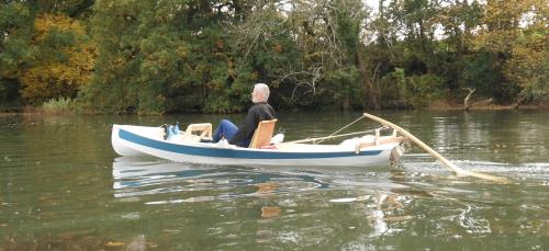 Chris W |
«
Return to Builds in Progress
|
1 view|%1 views
| Free forum by Nabble | Edit this page |