![]() |
Chris,
Paul Fisher has put the floor butt joint inside the foredeck buoyancy tank - out of sight is my guess. The side planks are indeed amusing. They are recycled from the Bee planks, which were extended from a Premise mockup They were taking up a lot of space on my sky shelf. The shelf is a 12ft x 2ft ladder frame suspended from the rafters by rope, for storing really, really long flat stuff. The 16ft planks also blocked out the florescent lights, so they had to go. The side forward joints will be hidden under the foredeck, the rear joints will be half buried in the rear seating and shadowed by the side decks. For the shrouds I thoroughly agree with doubling up to give a solid place to bolt the chainplates. Cheers Paul |
![]() |
Well, as I had hoped, that puts the 'men'
Firmly in 'Make do and Mend' Doesn't it? CW |
![]() |
In reply to this post by Paul H (admin)
Here is the Attenborough style shot after the animals have stripped a carcass:
![]() |
![]() |
But the net where the spinnaker used to be stored under the fordeck is still haning on in there!
|
![]() |
Finally all of the frame is disassembled. Any similarities to a bomb site are fake; there is a method to the madness.
I recovered the critical items: the King post to support the mast, the foredeck beams, the side deck beams that sweep between the foredeck and transom and the supports for the side deck. I can blend the old side deck supports onto the new plywood frames. ![]() I was able to split the keel away from the hog. Levering out the awkward screws in the brass strip means I can strip and clean the keel, then reuse it and cap the centreboard end grain. A hog is not required in Paul Fisher's design. The bottom end of the King post was damp, proving that it is worth the effort of stripping down the hardwood and rebuilding. Yes it refuses to die - and may have to be a permanent feature. ![]() Paul |
![]() |
In reply to this post by Paul H (admin)
Checking the old transom it didn't line up precisely with Paul Fisher's panel plans, so I cut a new transom using his plans. I think I will cut off the old hardwood strip and glue it onto the new transom.
Stitching progressed methodically and quickly. There is only one chine to fiddle with, that's why I think the Heron is such a good design - simple but good enough to race. ![]() ![]() For beginners who have limited experience of stitch and glue, one should start from the transom and stitch forwards in one foot steps either side. The idea is that the top panels will support the lower panels along their length - so when twisting the bottom at the bow the stress is evenly distributed, reducing the chance of snapping the wood: ![]() An original deck beam is keeping the panels apart. I'll make ply frames 1 and 2 and glue the original Redwood deck beams to the top. That's a good mix of a lightweight frame and authentic foredeck support. Adding frame 1 or 2 now will start the curvature 2 feet back and help the final bow stitching - otherwise the bow stitching has to take the extra strain of curving the whole boat. -Paul |
![]() |
This post was updated on .
Always rewarding to see how quickly a boat appears when stitching.
> On 22 Mar 2018, at 11:16, Paul (admin) [via UK HBBR Forum] <ml+s967333n4030540h53@n3.nabble.com> wrote: > > Checking the old transom it didn't line up precisely with Paul Fisher's panel plans, so I cut a new transom using his plans. I think I will cut off the old hardwood strip and glue it onto the new transom. > > Stitching progressed methodically and quickly. There is only one chine to fiddle with, that's why I think the Heron is such a good design - simple but good enough to race. > > > > > > > For beginners who have limited experience of stitch and glue, one should start from the transom and stitch forwards in one foot steps either side. The idea is that the top panels will support the lower panels along their length - so when twisting the bottom at the bow the stress is evenly distributed, reducing the chance of snapping the wood: > > > > An original deck beam is keeping the panels apart. I'll make ply frames 1 and 2 and glue the original Redwood deck beams to the top. That's a good mix of a lightweight frame and authentic foredeck support. > > Adding frame 1 or 2 now will start the curvature 2 feet back and help the final bow stitching - otherwise the bow stitching has to take the extra strain of curving the whole boat. > > -Paul > |
![]() |
I've almost stitched the hull at the bow. There is a lot of tension in the lower planks, but they are well supported on both edges:
![]() Since then I have read Paul Fisher's instructions! 😁 The curved 4ft girder that runs aft from the bow chine must be half-slotted to accept frame 1 at right angles. Also a rope 300mm from bow and 30mm below chine is used to pull the lower planks together (although stitching has almost done that). The girder and frame are dry fitted then lowered into the hull. The girder supports a flat top to form the bouyancy tank. Eventually that will create a very strong bow, much lighter than the orginal build. Paul |
![]() |
In reply to this post by Chris Waite
An update on progress:
Frame 1 has cut-outs to reduce weight and provide an open space above and a buoyancy tank below. I used my Bosch hole saw set to create rounded internal corners: ![]() Join the dots with a jigsaw, cut a slot halfway and the frame interlocks with the forward girder: ![]() Placed in the bow it will create a strong but lightweight monocoque. Frame 2 will have a cut-out in the top half; horizontal planking will create a buoyancy tank below. Notice I have screwed the original Redwood foredeck beams to the frames 1 and 2. However, they add so much weight I could switch to softwood to save weight. Softwood beams on the frames will still be strong, but I will reuse the original Redwood mast post which is a solid piece of timber to secure an anchor for example. ![]() Here are frames 3,4 and 5 that create seats/tanks similar to the Mirror layout, except the internal edge is straight not curved and the centreboard top is flush with the seating. A straight edge is easier to make and 3 or 4 removable panels can create a sleeping area. ![]() I used scrap ply for the frame cross sections. Temporary struts will brace the frame's shapes during construction. Frame 5 supports the edge of the back seat, 460mm from the transom. That is the aft position of the original rear seat. It should be possible to add a removable seat in front of the back seat, if sitting in the original position improves the balance whilst sailing [that seat can double up as sleeping support]. Finally a view looking back. You can see I have recycled the original Redwood side deck supports and epoxied them to the plywood bulkheads - I thinking I could varnish the exposed Redwood and paint everything else. ![]() -Paul |
![]() |
Looks excellent Paulie
I've still only got as far as a set of barge blocks for my next project - ![]() ![]() Took for ever burying the foundations - ![]() ....and what is more I don't think it will ever have a hull; just a deck, so it's as well I'm not thinking of taking it to sea. On the other hand I could start offering the Great Plains States a wide-gauge railway contract - ![]() Pity my name middle name is 'Grenfell' And not 'Brunel' really Christo W. |
![]() |
Come on CW own up.
Ruthie may think she's getting a new decking but we know what you're really up to. Very sensible to build your new boat shed with handy step thro' access to all domestic facilities. With the added bonus of less grass to cut its clearly a win win scenario. Grum. |
![]() |
In reply to this post by Chris Waite
Chris,
This video is all you need to follow in Brunel's footsteps, complete with colonial commentary! ![]() Paul |
![]() |
Actually Paulie
I'm thinking of handing over the business to my grandson. Not only is he a junior American and obsessed with trains, he's already in Atlanta; it's all downhill from there (320 metres above chart datum). Now Grum there's no need to be envious of my covert intentions until I own a double garage like yours. In the mean time, you just pop in to that centre of industry And get building yourself a boat You can sleep in CG |
![]() |
I've hit a problem stitching the bow curve and need some advise please.
Below are pictures of the bow area. You will see that frames 1 and 2 have curved bottom edges - there is bulge of 13mm for frame 1 and 7mm for the larger frame 2. I have put a thin fillet of epoxy on the front foot and dabs of epoxy up to frame 2. This is to stabilise the bow curve, stopping the highly curve panels slipping out of alignment The problem is that Paul Fisher's plans put the bottom panel butt joint 3 feet from the bow. Hindsight is wonderful ![]() That would thicken the floor between the centreboard and last frame - which is a good place to have a stronger floor. In the forward position the butt joint is going to curve far less than one layer of play. The gives a curve - flat - curve shape for the floor near the bow: ![]() The rear of the boat has flat floor frames. I think the bow section will have better curvature with one of: 1) Slightly less curve on the 1st frame and almost zero curve on the 2nd frame. 2) Lengths of 2x1 cut to a curve and screwed/glued to the butt joints from below. 12mm laminated could be very hard to bend though. 3) The 1st frame matching the natural stitched curve and a flat 2nd frame ![]() Another issue is how to support the hull. I currently have V frames near frame 2 and the final frame 5. In hindsight again some support under the hull middle may be needed; also curved support under frame 1. So what should I do chaps? ![]() cheers Paul |
![]() |
This post was updated on .
As I said in this subject on 12 March -
Butt straps this far forward on the floors is going to make bending difficult; having said that, I'm afraid I don't understand what the problem is now. Is it trying to get the convex curves of the bulkheads to match the less concave curves of the floors themselves where the two are meant to meet? If so, at the risk of putting this ace racing machine out of class, I would reduce the convexes of the bulkheads to match the floors until you can 'force' the bulkheads themselves into the right positions. 'Fill' any slivery spaces created by over-enthusiastic trimming and glass tape the bulkheads in place. Only you, I and your dear readers will know. I think that is something along the lines of your possibilities '1' and '3'. I suspect that Paul Fisher reckons to set the boat up with the butt straps only loosely (?machine) screwed in place so they can move sufficiently to allow for the increased curve induced by installation of the bulkheads themselves. 
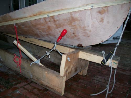
In regard to a building frame, I usually have at least a strong-back beam under the keel, to use for pushing and pulling and as a chart datum for measuring stuff from. If you want to try and force the floors to curve more then it is also possible to use a short timber baulk between the points of maximum curve inside the hull, then link it through the keel seam to the strong-back and wind down, very carefully (Crack!) with a threaded rod, or a Spanish windlass, until the bulkhead drops peacefully into place. Don't forget to put a wedge between the keel seam and the strong-back otherwise the whole hull will simply bow (pronounced either/both ways) to the power of your Spanish rod or whatever you use. If the epoxy tabs start to act up - cut through them and put the stitches back in until you have the shape you want. 
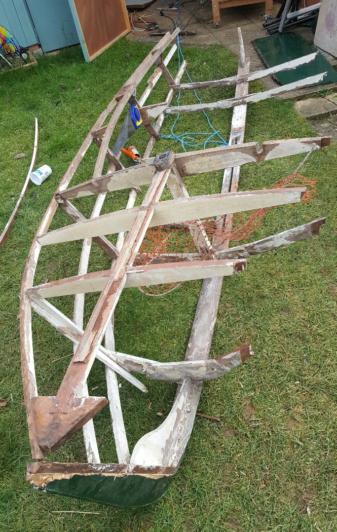
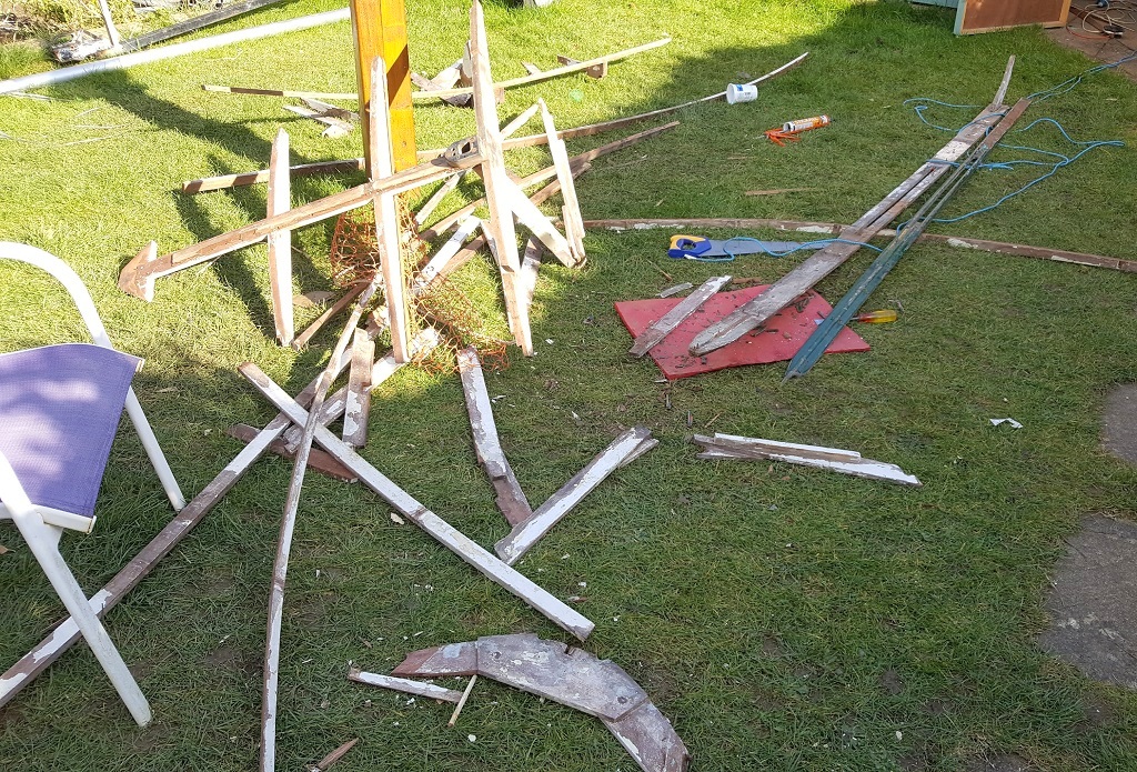
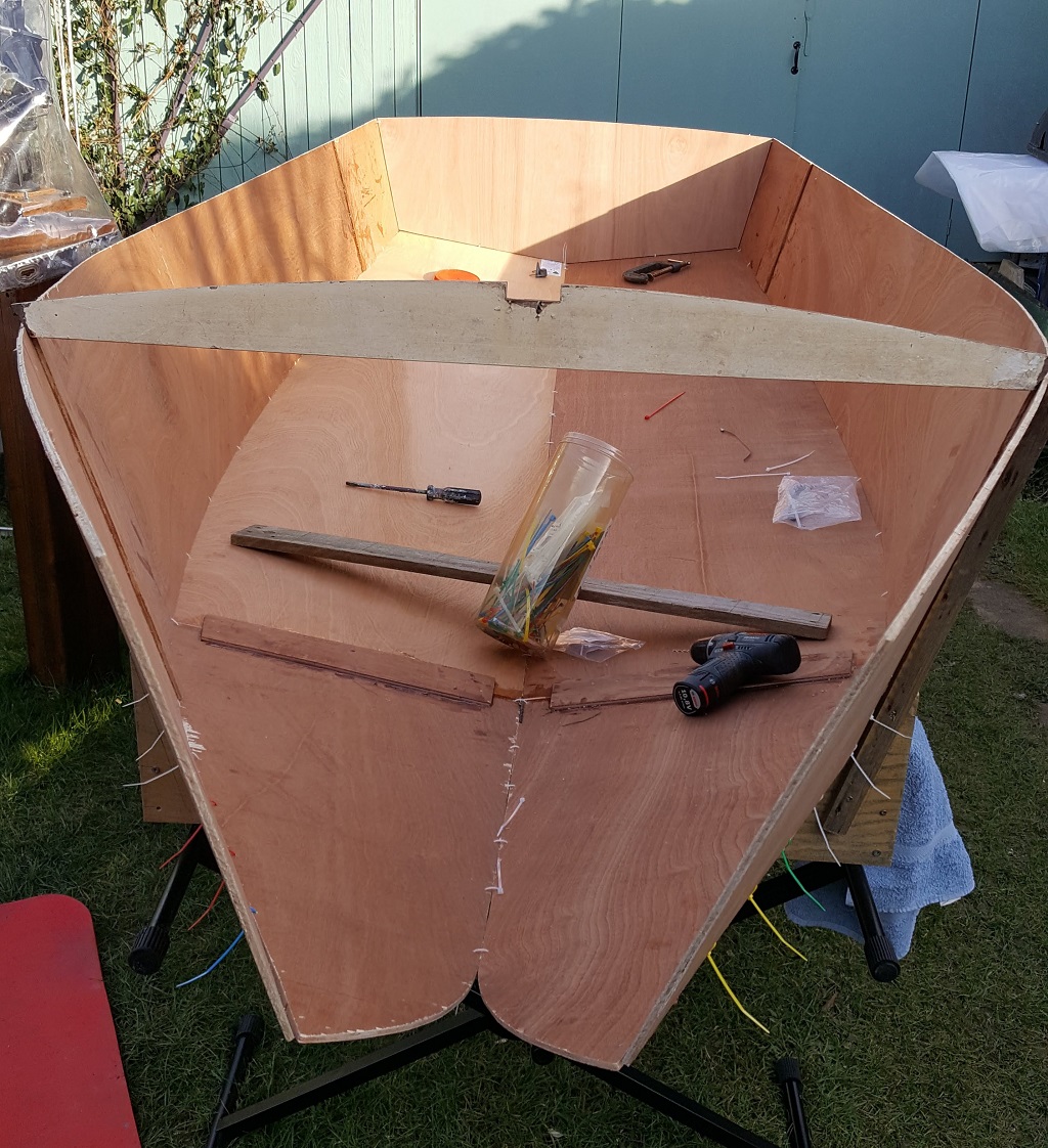
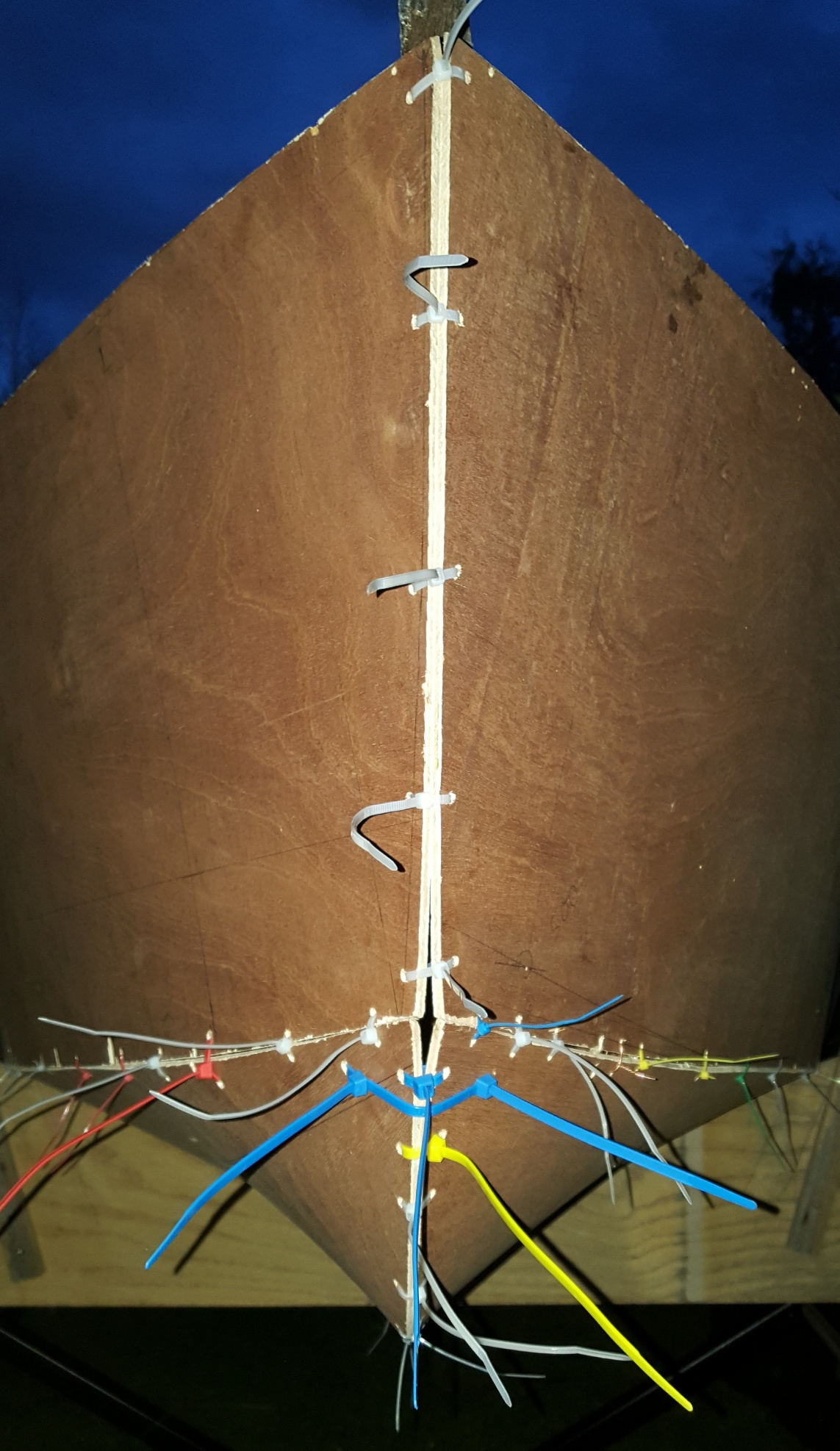
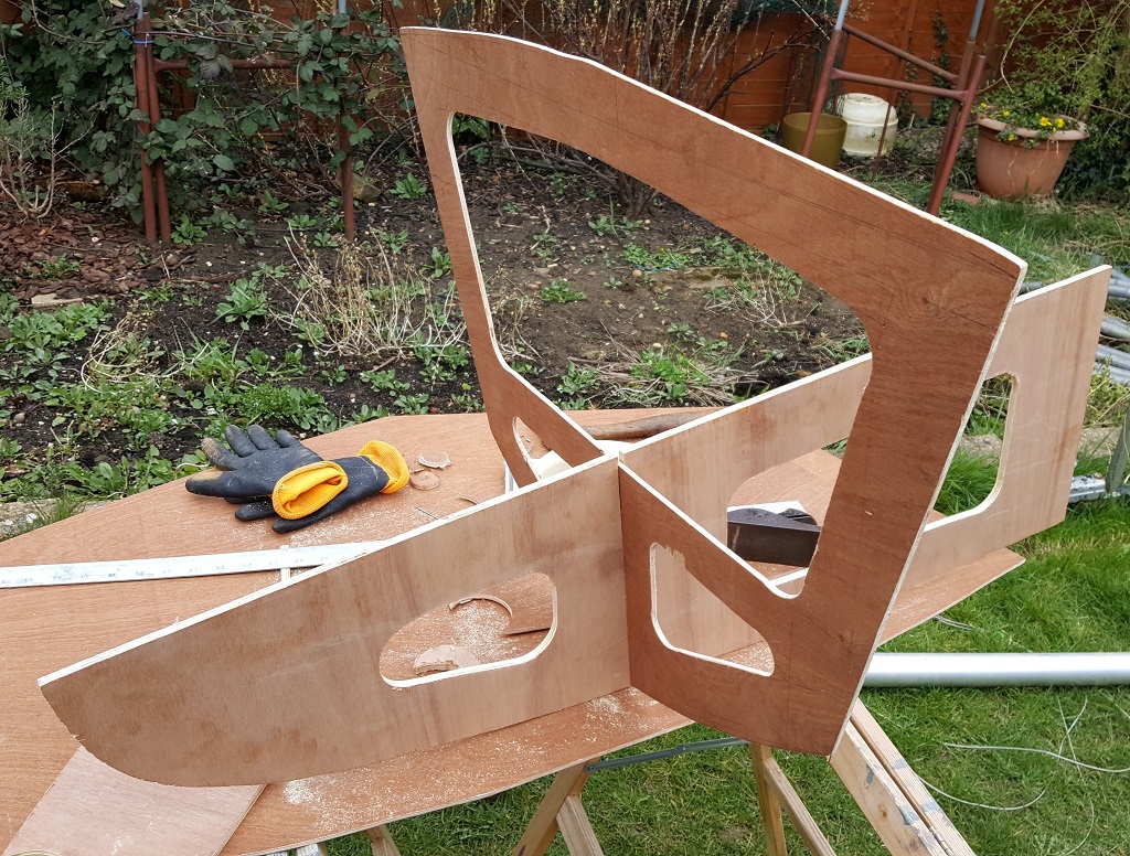
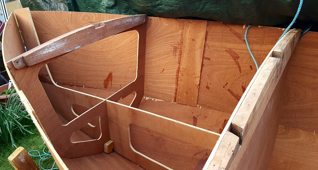
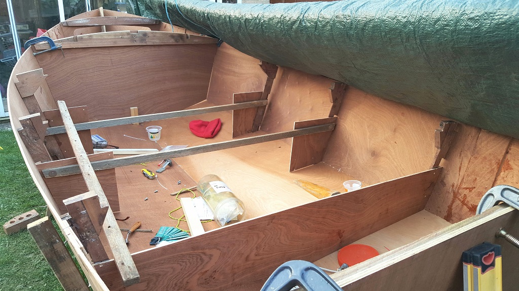
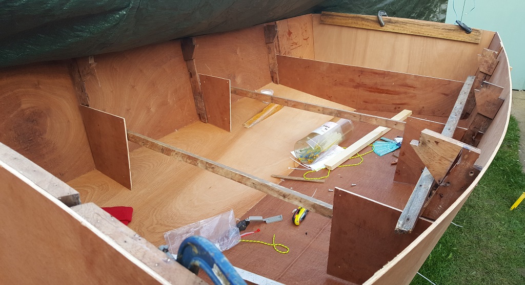
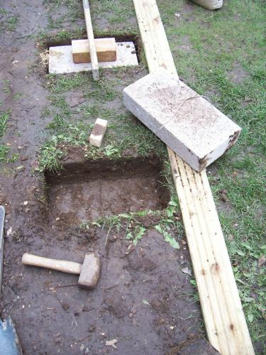
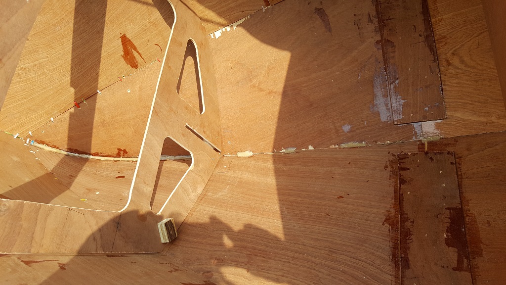
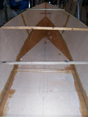
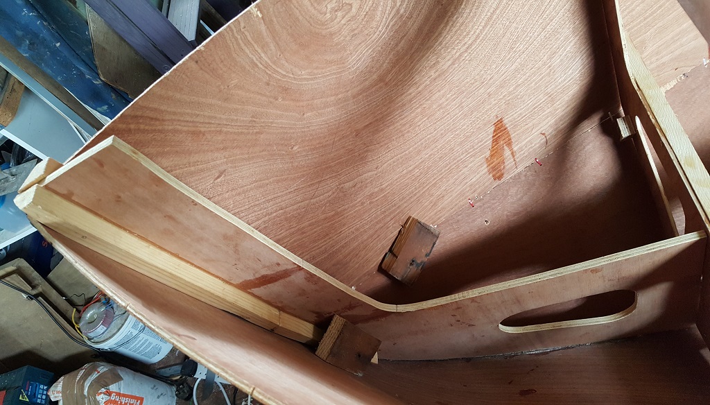
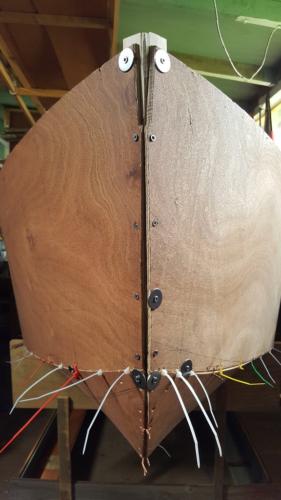
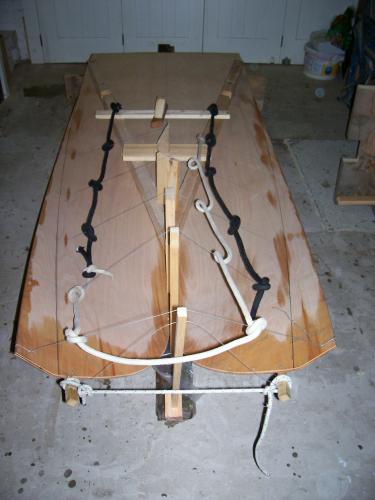
Here are some pictures of the entertainment I had forming Polly Wee's forefoot sections - ![]() ![]() 
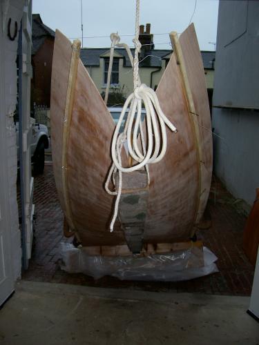
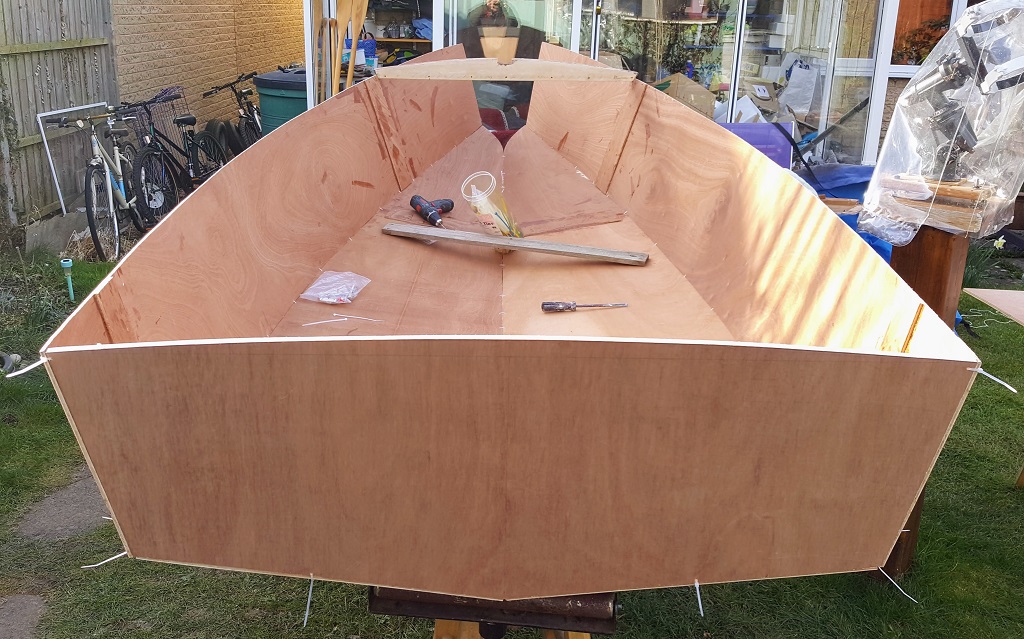
The black and white ropes were to discourage any snapping wire from interfering with my beauty (I lay a towel over a line hauling out the little gaffer at Barton once and just as well, because it snapped and tried to take my head off, but the towel was too quick for it and acted as an air brake.) ![]() ![]() 
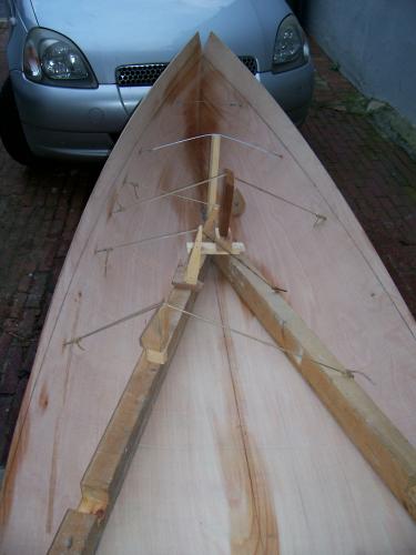
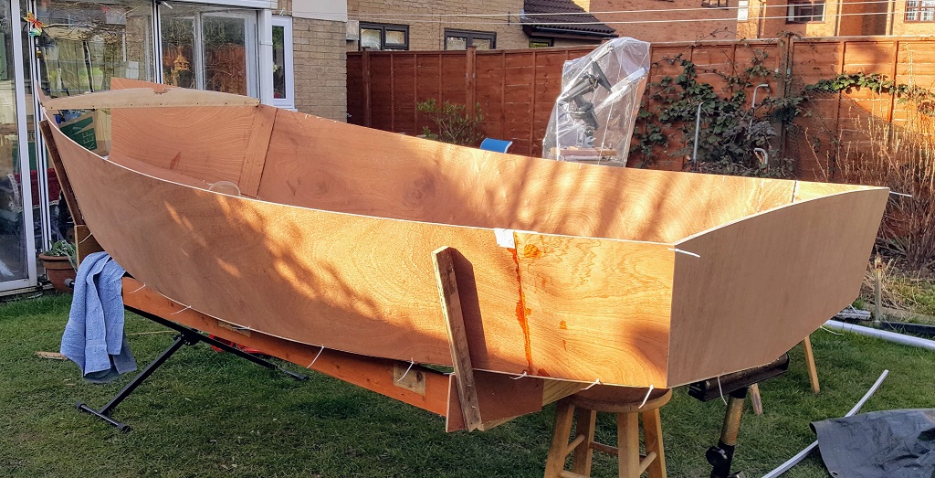
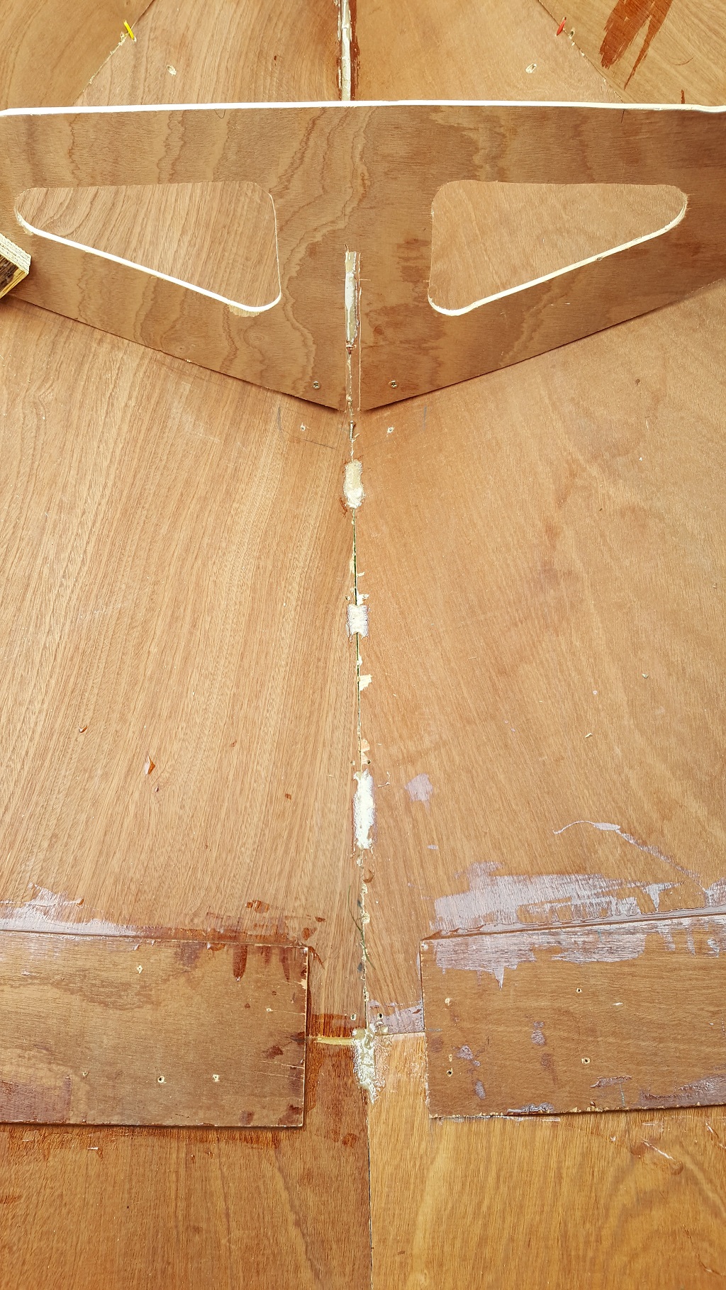
Note the last picture has three Spanish windlasses in it Much forcing of the ply Such fun CW |
![]() |
Chris,
Thanks for the feedback and advice. The horse had truly bolted by the time I posted the pictures - so your wise words were unobtainable. The current problem is the butt strap is only 6in from the main bulkhead with a 7mm bulge (away from a straight line). So the butt strap needs a curve of about 10mm to blend into the first frame. I'll experiment with a permanent curved mold each side, to encourage each butt strap to bend. Screws with large washers can pull the ply towards the mold. If it works with a dry fit, it can be epoxied permanently in place. However if there is a loud CRACK!, I have a beer waiting in the fridge. 😀 Paul |
![]() |
This may be a mad idea, but, from a purely structural view, the butt straps don't really do much for most of their thickness.
So, how about hitting the lower part of the butt straps with a belt sander and reducing their thickness by at least 2/3rds? That would increase the local flexibility a bit, and if you're concerned about lost strength ( and personally it wouldn't bother me at all at this stage) then just add an extra layer of glass tape and resin over that area, after pulling it into shape. If it were me, then I'd probably reduce the thickness of the butt straps even more, and then just add a bit of glass and resin to more than make up for the very small loss of stiffness and strength. Remember that it is only the outer and inner faces of the skin of a boat that have the highest stresses, the stuff between the outer ply veneer and the inner is really just there to keep the two load-bearing veneers apart. |
![]() |
I agree with Jeremy
Harking as always to my own builds, Polly Wee has no butt-strap on the side strakes. The seams are deliberately placed two thirds of the way forward, where there is least bend anyway and I fixed temporary, external straps (with polythene sheet under them to be able to release them after I had the strakes properly in place) and had stagger-double taped the inside of each. In respect of her having an intentional flat bottom, again with the seam at the point of minimal bend, two thirds of the way aft, I did permanently fix in an internal butt-strap to strengthen the floor for taking the ground. Here is the inside of the hull at that stage, with several temporary struts, (OK, 'sticks' then), to hold the shape while I epoxied throughout to encourage eternal maintenance of her fabulous form; (that is 'eternal', not 'external') - ![]() Note that I also use temporary inwales while building and these are eventually removed, in favour of permanent external rubbing strakes, as the build progresses.... Leaving no 'wales' at all All very light In fact Chris W |
![]() |
Jeremy, Chris,
Thanks for the good ideas. I agree in hindsight about the butt straps; I think a simple and quick 45 degree scarf using my table saw or band saw would have been strong enough in this case. One could strengthen the whole area forwards with 4mm ply after gluing the chines and keel. Supporting the butt joint at each end, hand pressure can yield a curve. So I'll cut the required curve on 2x1 using my bandsaw. Screws and washers should pull the butt joint to the curve OR it all explodes! Temporary inwhales is a great idea; especially as I have original Redwood inwhales pre-bent for a few decades. Although the frames 2ft apart form the shape quite well. I've got the transom to bow diagonals close within 3~4mm, the panels have been temporarily screwed to the girder. Pictures in the next post. Paul |
![]() |
Some pictures of the main girder and interlocking frame1.
I have a cleat on frame 1 to keep it straight and support the shelf (to be fitted later). A lot of time was spent gluing, cutting and sanding wood either side of the girder, to create a bevelled curve that fits the bow. As you see something went wrong with the height of the bow ![]() There are a couple of blocks to hold panels together in high stress areas and fix a minor crack in the starboard panel. ![]() This was a good opportunity to screw the panels in place to check alignment - it's remarkable how that makes the whole boat stiff. 5mm penny washers are so useful for spreading the load. ![]() -Paul |
Free forum by Nabble | Edit this page |