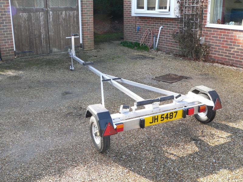
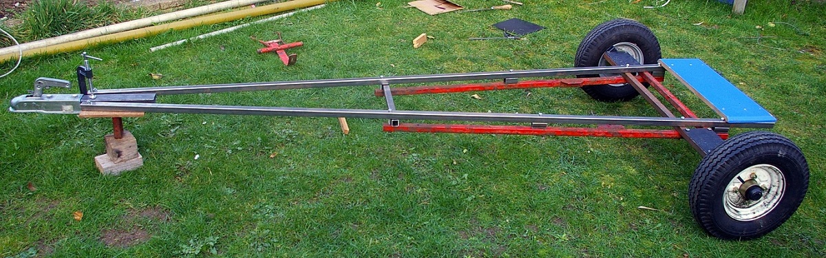
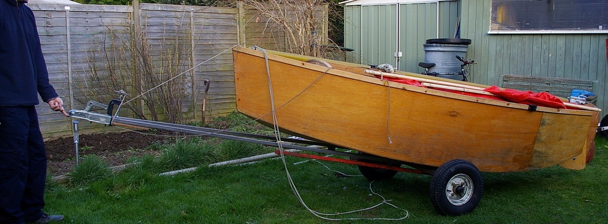
Illusion's DIY Trailer

12
12

|
Paul H (admin) |
Illusion's DIY Trailer
|
|
|
|
Paul H (admin) |
Re: Illusion's DIY Trailer
|
|
|
|
Anders |
Re: Illusion's DIY Trailer
|
|
|
|
Chris Waite |
Re: Illusion's DIY Trailer
|
|
|
|
Jeremy |
Re: Illusion's DIY Trailer
|
|
|
|
Paul H (admin) |
Re: Illusion's DIY Trailer
|
|
 ).
).
|
|
Jeremy |
Re: Illusion's DIY Trailer
|
|
|
|
Paul H (admin) |
Re: Illusion's DIY Trailer
|
|
|
|
Jeremy |
Re: Illusion's DIY Trailer
|
|
|
|
Ratcatcherjohn |
RE: Illusion's DIY Trailer
|
|
|
|
Paul H (admin) |
Re: Illusion's DIY Trailer
|
|
|
|
Port-Na-Storm |
RE: Illusion's DIY Trailer
|
|
|
|
Paul H (admin) |
RE: Illusion's DIY Trailer
|
|
|
|
Ratcatcherjohn |
RE: Illusion's DIY Trailer
|
|
|
|
WalneyJohn |
Re: Illusion's DIY Trailer
|
|
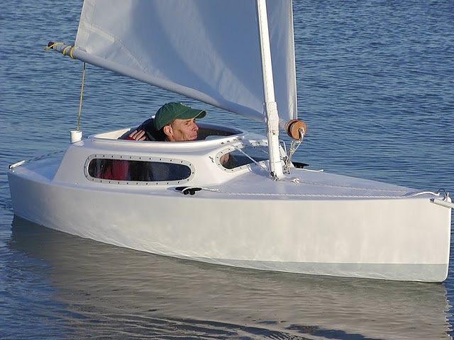
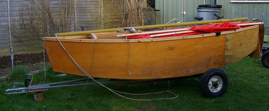
 after a days sailing
|
|
Jeremy |
Re: Illusion's DIY Trailer
|
|
|
|
Paul H (admin) |
Re: Illusion's DIY Trailer
|
|
|
|
Randonneur |
Re: Illusion's DIY Trailer
|
|
|
|
Paul H (admin) |
Re: Illusion's DIY Trailer
|
|
|
|
Paul H (admin) |
Re: Illusion's DIY Trailer
|
|
| Free forum by Nabble | Edit this page |