The "Aerowherry" a lightweight rowing boat (was going to be a canoe........)

12345
12345

|
Chris Partridge |
Re: Unusual lightweight canoe
|
|
Sorry to have confused you, Brian. Don't take anything I say as gospel.
Ideally, everyone should have a sliding seat boat and a fixed seat boat and use the one that seems appropriate at the time. I just feel that people are far too respectful of sliding seat rowing, to the extent that the fixed seat option often seems to get forgotten. Sliding seat rowing is a lovely action, as you have discovered. So my feeling is that you should do exactly what you want to. The essential thing is to get out and do it. How is your Snipefish getting on? I would love to come round and give it a solid workout. |
|
|
Chris Partridge |
Re: Unusual lightweight canoe
|
|
In reply to this post by Jeremy
Sliding riggers are very good because they prevent hobby-horsing, which is significant in a relatively short boat. The mechanism is quite complex, however, and transfering the load properly from rigger to boat is difficult.
I really like the Clovelly Sculls system, and the Piantedosi sliding rigger unit looks good too, though I have never tried it. |
|
|
Chris Partridge |
Re: Lightweight rowing boat (was Re: Unusual lightweight canoe)
|
|
In reply to this post by Jeremy
You can hire pipe benders from Beavers very cheaply (£8 a day). One of them would get through that lot like a dose of salts (assuming your pipes are a standard plumbers' size, of course).
|
|
|
This post was updated on .
In reply to this post by Jeremy
Hi Jeremy, I printed off the hull lines and those of Sweetbria to spend some time just absorbing the lines.
At first, the front half of "has she a name yet" looked slightly larger than the rear half. Almost the other way round on the overhead plan view. Low point of the hull more forward than mid point and widest beam further aft than midpoint. Very interesting. In contrast, Sweetbria is much more conventional, but less interesting. Looking at the ahead/astern view, I can see a high prismatic hull, quite a flat stern to stop her bobbing. You should see Chris on full power in his Sprite. Then I can see a long very clean run aft, and just how narrow her forward sections are. Then the higher bows make sense too, and will work well in our short Solent chop. She looks like she could be quick through the water, as your resistance results show. Her finer bows and flatter stern sections are like Iain Oughtred's sliding seat Snipefish http://jordanboats.co.uk/JB/IainO_Catalogue/Snipefish.pdf Her strong sheer might look even stronger in 3D. Quite a bit stronger than Sweetbriar. Slightly doryish? However for the use I would like to put her to, those higher ends forward and aft will be very welcome. You see, I have lived on a cliff top for over twenty years, and I really want this year to sort out a boat I can carry from home, down the cliff steps and yet, the boat has to cope with launching in and through waves. I cannot use a kayak because trying to roll one made my balance problems much worse, and so far I have never found a rowboat I could carry down the steps. The geodesics just don't look as if they would cope with the sea conditions. and I am just not a woodworker either. So, when you are ready, and happy with her handling, and that she is "right" I would love to order the tubing from Chandlers Ford, pop over to pickup the jigs or use the jigs with you so you keep your hands on them and come home and build a boat that at last I can handle down the steps and row along the beach. Brian |
|
|
Kudzu has just posted an interesting piece about realising how high the outriggers have to be when using John Welsford's placement guide. Here's his drawing
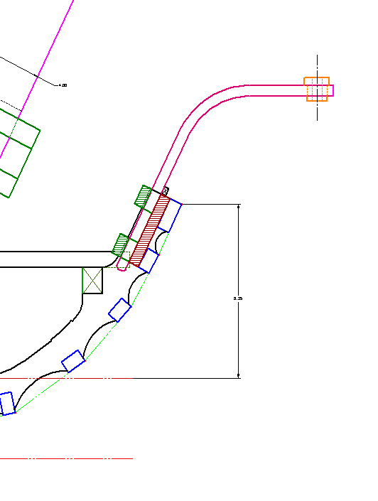 Chris has blogged John's good advice here http://rowingforpleasure.blogspot.com/2009/01/john-welsford-on-crusing-rowboats.html You can understand why this kind of unified assembly works and putting this inside the car and the hull on top makes sense.  There is an Open Water Rowing Facebook which has some good words on fixed seat rowing set up http://www.facebook.com/pages/Open-Water-Rower/134528159929424 "Firstly, 48 inch span pin to pin and 7.5 foot oars are the ideal. Dont go by the oarmakers advise. go for 7.5s, if your span is between 42 and 50 inches. The fixed oar collars allow a precise repeatable stroke. Dial in the position in so that the handles are at shoulder height at the beginning of the stroke (catch) and clear your ribs by an inch or so at the finish. This allows you to lean back a little and "hang from the handles" at the catch. Its more dramatic in a surfboat and subtle in a lighter boat. Handles should be 4-18 inches apart a the catch, and only overlap during recovery, usually a handle's width. As there is no load during recovery more or no overlap is permissable, let the height of the pull and the oar balance determine this. Move the collars a half inch at a time, using a bicycle Y wrench on the hoseclamps instead of a flatblade screwdriver. If it doenst dial in, distance from the rear of the seat to the oarlocks (14-17 inches) is another variable as is distance to the footbraces. Getting it right is more important than blemishing your varnished gunnels with a few extra screw holes. Spoon blade oars have never felt as smooth as flat blades, stick with shaw and tenney or get Fancy and sand the blades thinner. If its not thin enough to break its not thin enough. Shaw and tenney insists on tapered handles on oars 7.5 foot and above. Sand them to barrel shape or specify barrel shaped handles. Tapered spell carpal tunnel....." |
|
|
Thanks for the useful links and the observations about the hull shape. I'm definitely an amateur in this boat design lark, so I am trying to adapt my understanding of aeroplane design to building a boat. I've tried to keep the wetted area low, whilst not making the boat too tippy, always a bit of a compromise. The metacentric height is OK (I hope) for such a fairly narrow boat, at around 360mm. This should give around the same stability as a fairly broad open canoe, from what I've researched so far.
The idea behind putting the maximum draught slightly forward of the centreline is twofold. I wanted to minimise form drag, which means having as shallow an angle on the run aft as possible, but more importantly I wanted to have all the longitudinal tubes bent in plain arcs, with no complex curves. These arcs are defined by three points, with the centre point always falling at the lateral centreline of the boat. This is more for ease of building than anything else, as it means that a temporary central support at the centre frame, plus fixing the ends at the right points, will automatically produce the correct fair curves. I've spent (some might say wasted.....) a few hours today by over-thinking the problem of bending the keel bend at station 5. Thinking that the tube would collapse badly if I tried to just pull it around a 1" post, I spent a couple of hours making a tube bender for 1/2" tube, with a 1" inner bend radius (this is way smaller than any commercial benders will do). This turned out to be a waste of time, as the distortion from just pulling the tube around the pillar is modest and acceptable. The wasted time meant that I only had a couple of hours to make frames today, but I managed to get four of them made:  Inevitably the first frame took over an hour, whilst the last one only took just over ten minutes. I hate it when you only get good at doing something just when your near the end of the task. Anyway, here are some tips on how to bend alloy tube neatly. First of all, the tube needs to be fixed firmly at the keel point of the jig: 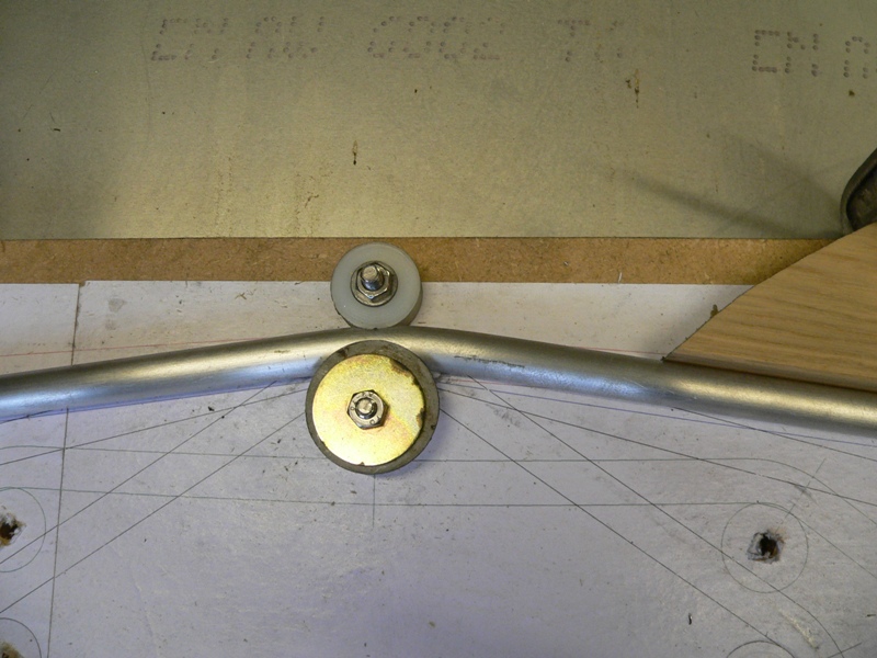 I fitted a second, shaped, roller to hold the outside of the tube firmly in place then clamped the tube down with a big washer and just pulled both ends of the tube around until it was bent to the correct angle. If over-bent it's easy enough to just unbend it a fraction. Next, a block of wood was clamped against one edge of the frame to hold it tight up against the next bending post. At this point I found that it helps to stiffen the frame tube so that it only bends where you want it to. By happy coincidence, ordinary 15mm copper water pipe is a nice sliding fit over the alloy tube and does the job admirably: 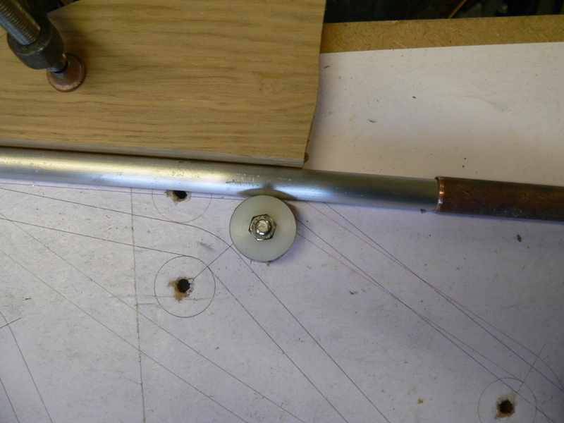 I discovered that bends were a bit neater if I pushed the copper pipe fairly close to the bending post, but only towards the end of the frame bending session. Here's a close up of the finished chine bend: 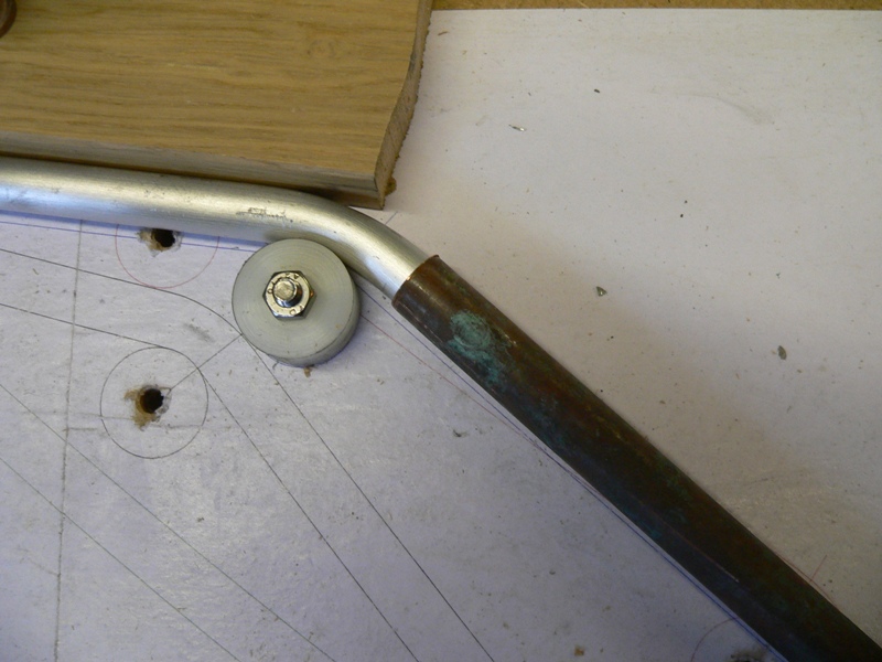 Total weight of the four frames made so far is 700g, so I think I should be able to make all the frames plus maybe the transom come in at under 1kg, pretty much on target for my 10kg finished weight. Tomorrow I will get the last frame bent and make a start on a strong back to start the build. Jeremy |
|
|
Wow, 10 kg.
I have 4 smallish Ortlieb drybags. Might need two filled with bubble wrap to keep her on the surface if she tips, and perhaps the other two filled with water ballast so you can actually climb in and sit down! I had been wondering how the tubes could be bent without bowing, now I know. Do you have a name lurking in the background for this design? Here are some "water" names, http://hasani.net.phtemp.com/water.html The Greek sea nymph names might match for such a light boat. My last Scow was called Ula, which is on the Celtic list and means jewel of the sea which suited her well. Brian |
|
|
I haven't really thought of a name yet, but I think one will surface before too long.
The tube bending was simpler than I thought it might be, but needs a fair bit of force. It's surprisingly tough stuff, but I suppose this isn't really surprising as the tube is very similar in size and section to that used to make camp beds. She will probably float if I just squirt some foam into each of the tubes, as they should displace more than 10 litres or so combined. Might be a quick and dirty way of providing flotation without adding much weight. Alternatively I may just include some glassed over foam blocks at the bow and stern, and perhaps make the floorboards and thwart/seat the same way. Jeremy |
|
|
After a week of progress being interrupted by domestic chores, I got back to working on the final aspects of the design this afternoon. As always, the devil is in the detail and I spent hours pondering over ways to easily make the stem and stern.
After a few failed experiments, I've decided that the transom will be made from a piece of 52.5mm thick extruded polystyrene foam (Knauf Spaceboard loft insulation, from B&Q). I've made a couple of templates to shape the interior and exterior faces and will layup epoxy glass over the foam. The plan is to then bore holes into the foam, through the epoxy glass skin, to accept the gunwale, stringer and keel tubes. These will be bonded and riveted to the glass/foam. The attachment of the tubes to the stem is proving to be a harder problem to solve, but hot favourite solution at the moment is to have a sheet alloy stem with horizontal pieces of sheet alloy riveted to the tubes and fitting into the stem via slots. The vee of the stem will be made from a couple of bits of foam glued to the sheet stem piece on either side, shaped to fit and then covered with epoxy glass. Next stage is to get on and make the transom and stem tomorrow, so with luck I may have some more photos of progress then. Jeremy |
|
|
This post was updated on .
The more observant may have noticed that I've changed the thread title, as I thought it was about time it stopped being called "the boat", It's a blend of aeroplane construction techniques and a traditional wherry hull form, so the Aerowherry it is.
I managed to get the transom finished, not as easy as I envisaged and a little heavier than I would have liked, but it will do the job well. I used a piece of extruded polystyrene insulation foam, purchased from that well-known purveyor of boat building materials, B&Q. The first task was to transfer the lines from the drawing to each side of the foam accurately. I made some templates from aluminium sheet, that I could bolt through the foam and maintain accurate alignment. These worked well, as I could also use them as a guide for a sharp carving knife to get the odd shape to the edges: Having cut the foam to shape, I then needed to sand the edges to smooth radii and cover the foam with glass cloth and epoxy resin. This is the same technique that Burt Rutan pioneered many years ago to build his famous Quickie and Varieze home built aircraft, carved and sanded foam covered with epoxy glass. It makes an exceptionally strong structure and yet remains reasonably light. The downside is the filling and sanding required to get a fair surface, but for small parts like this is shouldn't be much work. The resin has cured enough to show the partially finished result: I reinforced the keel point with a couple of extra layers, so there will be some more filling and sanding needed in that corner to get it fair. The next job will be to bore holes in the inside face for the gunwhale, stringer and keel tubes. These will be bonded into the transom and also secured with stainless rivets set into countersunk holes in the epoxy glass skin, which will be filled and sanded smooth before the fabric is applied. The weight of the transom as it stands is 423g, but I expect it will be around 480 to 500g by the time it's finished. It is probably massively too strong, as I used two layers of 300g/m² cloth on either side, overlapped around the edge and doubled up on the lower corner. I have a feeling that one layer on each side, with perhaps a layer of unidirectional tape wrapped around the edge, would have done the job and saved a little weight. I'm going to experiment tomorrow with making the stem the same way. Carving and glassing the foam is very quick, it's making the templates that takes the time. Excluding making the templates, the transom has taken around 1 1/2 hours so far, plus some hanging around waiting for resin to cure (made worse because I've only got slow hardener in "stock"). Jeremy |
|
|
I managed to free myself from domestic chores for an hour or two today and made the stem. The technique was the same as that used for the transom, carved pink foam covered in epoxy glass.
In this case I cut two pieces of 52.5mm thick foam out to the profile shape of the stem and glued them either side of a similarly shaped piece of 1/16" thick epoxy glass laminate board. The idea of this central web is to add strength to withstand the inevitable bang right on the point of the bow. I also wanted to have an additional way of stiffening up the attachment of the keel tube to the forward end of the gunwales, rather than rely on just the foam and the outside epoxy glass layer. Just as with the transom, I made an alloy template and used this to carve the foam to shape, followed by some rough sanding to get it to the final shape. The foam was then glassed over, with some extra layers right on the bow to give added impact strength. Here's a couple of photos: 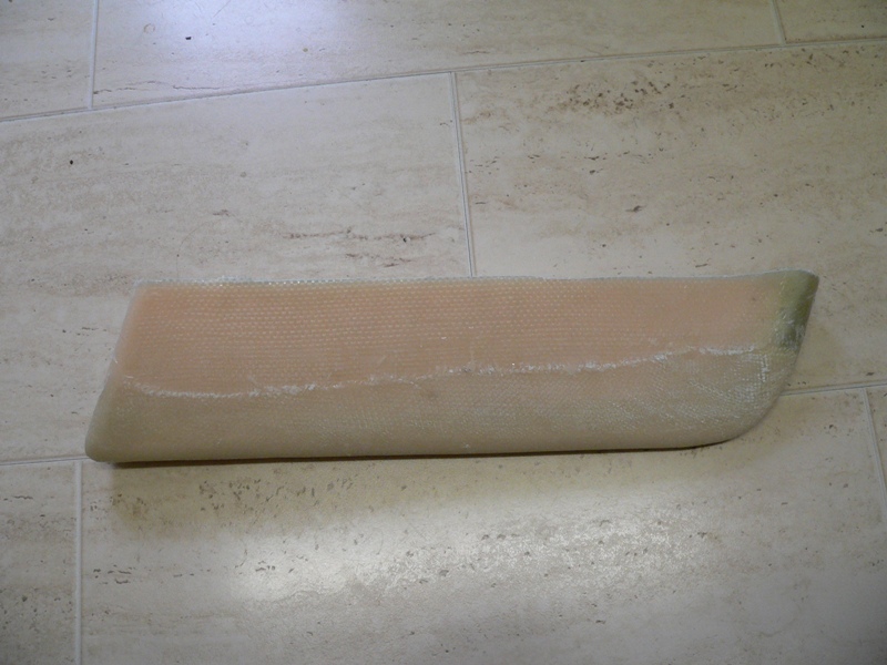 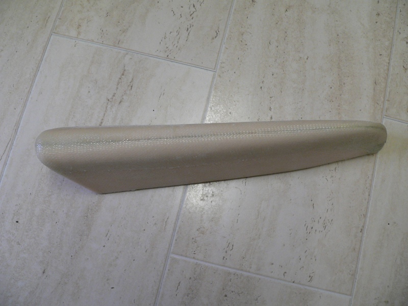 I need to glass the aft face and drill the holes for the tubes (the keel tube will fit into the moulded socket that's already at the base of the stem), plus add a skim of filler and sand the surfaces smooth enough for fabric bonding and the stem will be finished. Whilst waiting for the resin to cure, I popped down to Homebase and bought a sheet of MDF, sliced into 6" wide planks. I've glued these bits up into an I beam, with a hollow central web, that's 16ft long to form a strong back. Hopefully it should be straight enough and strong enough for the job. Jeremy |
|
|
This post was updated on .
Jeremy, how are things going?
You might have already seen Chris(P) has a very interesting blog entry yesterday showing a folding skin on frame rowing skiff with a taught zipped cover. Alloy tubes and ply frames. http://rowingforpleasure.blogspot.com/ Brian |
|
|
That's interesting, Brian. From the photo it looks as if the size of the stringer tubes is pretty close to the same size as mine, which if nothing else is a confidence-booster that I may have got it right.
Progress has been slow this week, with domestic tasks getting in the way too much. Last weekend I made a drastic decision (based wholly on the size of my garage/workshop) that 16ft is just too long. I'm part way through shortening the boat to 4.8m, which should (I hope) allow me to work on it a little more easily. This conveniently means that the frame spacing now comes to a nice round 800mm, too. I'm not changing anything else, just squeezing all the frames together a bit. I tentatively plugged the gunwale tubes into the holes in the transom this afternoon, put a suitable spacer bar between them at the mid-point and pulled the bow together and was pleasantly surprised to find that the 1" tubes take the curve easily and very nicely. I was going to build the hull right way up, mainly so that I could more easily fasten the frames to the stringers and keel, but have now decided that it will be easier to build it upside down and just put up with having to drill upwards to put the rivets in. Building it upside down has the advantage of being able to make sure I don't build a twist into the hull by accident and it will be easier to keep the stem and transom fixed securely to the strong back. Jeremy |
|
|
Having completed another round of household chores, plus with the onset of weather warm enough to use epoxy, I decided to spend most of the day on the build. All the parts were ready, so the first thing to do was bond the keel and gunwales to the transom and stem with epoxy and microfibre mix, and then wait for the epoxy to cure enough to get on with fitting the frames. Luckily the epoxy went off by about 12.00, so after lunch I decided to fit the frames. This was really amazing, as by 14.00 I had all five frames riveted in place and the whole thing started to look boat like.
As I still had an hour or two before SWMBO comes home, I decided to mix up some more epoxy and bond the stringers in at each end. Before the epoxy set I managed to drill through each frame into the stringers and rivet them all in place. This is the result of around 4 hours work today: 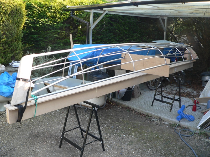 Here's a shot showing the neat way the frames fit into the gunwales: 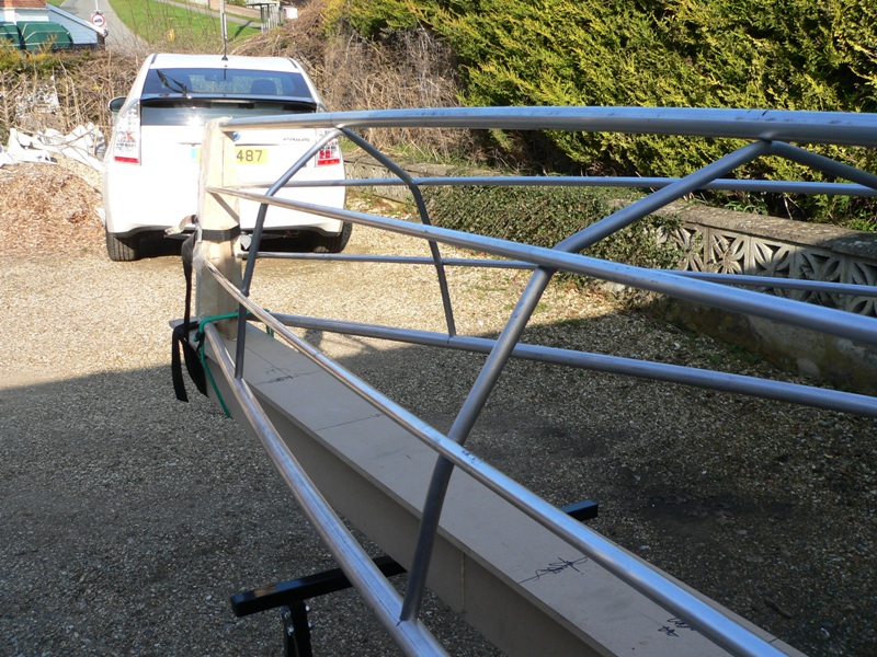 The frame is now essentially finished, almost ready for covering. I need to fair the tubes to the stem and transom so that the fabric lies neatly and do a bit of sanding, but that's the hull mostly complete. It has to be one of the fastest ways of building a boat around, I think (if you don't count the hours on the computer doing all the CAD stuff!). Jeremy |
|
|
That's amazing.
When SWMBO came home, and asked "Well what did you do whilst I was out?" You could reply "I built a boat!" Terrific. Brian |
|
|
She did sort of notice it as soon as she came home, as it's hard to hide a 16ft boat! I will admit to being amazed at just how quickly a pile of bits became boat shaped, it was really very satisfying to see the shape I'd only imagined on a computer screen appear in real life so quickly.
I was planning on doing some filling and fairing this morning, but last nights sub-zero temperature has ruled that out for a while, so I shall have to get on with finishing off the cordless challenge propulsion system. BTW, Pete has asked for a write up on this "skin on tin" (his name!) design, so I am trying hard to take lots of photos as I go. I made a change to the way the gunwales fix to the frame ends by using home made alloy expanding plus, rather than plastic wall plugs. 3/8" bar is a tight fit into the 1/2" tube ends, so I drilled a 4mm hole in a short length, ran a centre drill down one end to make an internal taper and then roughly hacksawed four slots to allow the plug to expand inside the tube. The result is an extremely strong attachment. Here's what the new bits look like: 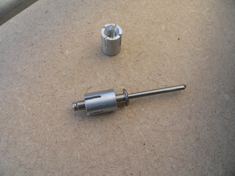 Jeremy |
|
|
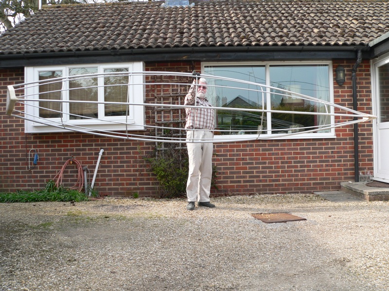
I managed to get the frame off the strong back today and have rough faired the transom and stem. Only about an hours work, I'm now waiting for filler to go off. I took a couple more photos that show the hull frame a bit more clearly. First, the obligatory shot that's needed for all lightweight boats, the one where I'm holding it with one arm outstretched. There can't be many 16ft boats that you can lift with one hand.
 Here's an end-on shot that shows the shape fairly well: 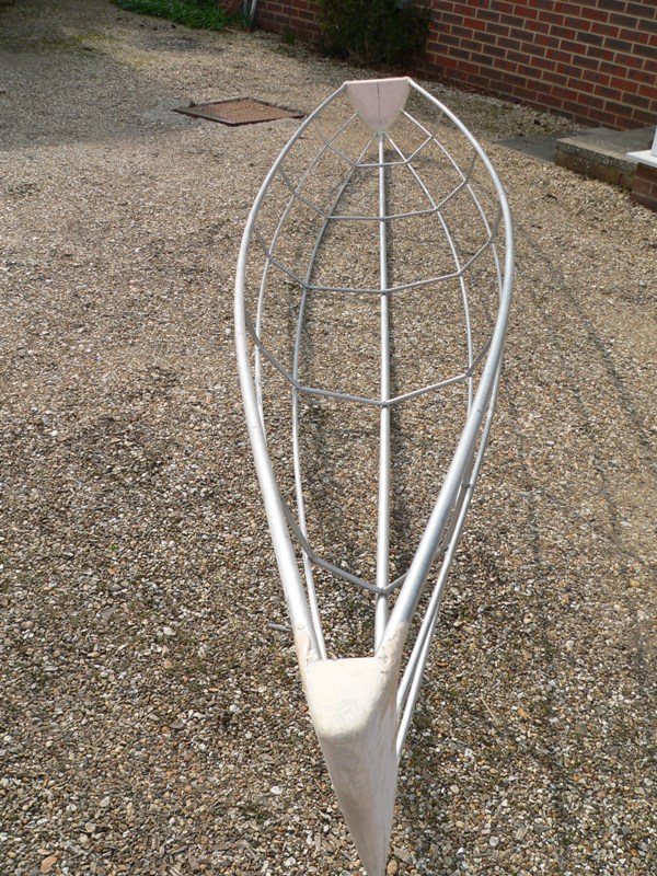 I won't get any time to do more on it until next week, as I have a stack of other things to finish off, but if the weather is reasonable I should get the frame covered one day next week. I can then move on to making the bits up to row it - I'm planning something slightly unusual and sticking with the "no wood allowed" theme for oars! Jeremy |
|
|
It looks really good. You must be well pleased.
Here's an article about setting up the rigging which might be useful. It's for sliding seat but has lots of good advice I think? http://arcrsa.blogspot.com/2007/05/rigging-your-single-scull.html Just a thought, some of the Yostwerks SOF, (or SOT), builders wrap their frames in pallet wrap/cling film to try the frame on the water before final covering. Brian |
|
|
In reply to this post by Jeremy
Looking very good. This way of building is going to start a whole new trend! Tim. |
|
|
Thanks folks, I have to say that this build has exceeded my expectations. I've never built a boat from scratch before, let alone designed one, so for most of the bits to fit together and produce such a nice looking shape has been pretty rewarding. I think I'm going to add two tubes between the gunwales at the frames at either end and add some fabric covering to form two small cuddys. These will have a secondary purpose in that they'll give something to hang on to to lift the boat up at either end (not that lifting it up is exactly hard).
I'm pretty sure I'm not going to make my 10kg target weight, unfortunately, but I don't think it will be too much heavier than that, maybe around 12kg or so. Even uncovered it's light enough for the wind to blow it around; I have to keep the frame tied down to work on it. As the frame has turned out much better than expected, I've decided to fork out on some heavier duty Dacron for covering it, as it seems daft not to make a proper job of it now. The cloth I've already got is Polyfiber 1.7oz/yd², intended for use on very light aircraft. I've just ordered some 3.4oz/yd² Ceconite 101, which is the stuff used to cover aerobatic aircraft and things like Dakota control surfaces. It is about twice as strong as the lightweight Polyfiber cloth and significantly more resistant to being punctured or torn. Coupled with reinforcing tapes bonded along the keel and stringers this should make for a much tougher covering, albeit at the cost of adding around 500g of extra weight, (and relieving my wallet of an extra £50 or so). If the planned cunning rowing gizmo I have in mind works, I might even contemplate doing the Thames Raid using this boat rather than the electric Winsome. Doing this would certainly ease the logistics, as it would mean only bringing one boat to Beale Park (and not needing to bring the trailer), plus I'd not need to take up a mooring space at overnight stops, either. Jeremy |
«
Return to Builds in Progress
|
1 view|%1 views
| Free forum by Nabble | Edit this page |