CNC Plywood cutting

1234
1234

|
|
This post was updated on .
I have moved this to another section of the forum since it probably makes sense to keep the Meetings section only for discussing arrangements for meetings/events.
Thanks Paul for your expert advice. From what you say I think I had better not be in the vicinity when the routing is done - I can envisage pieces of plywood and router cutter flying in all directions! I looked on Google and found that just in the Devon area there are several firms offering CNC cutting services. I phoned one of them yesterday and after I described what I wanted the owner said it would be 'no problem at all'. I haven't actually sent him the dxf file yet, I might do that today, maybe he will have a different opinion when he sees it. I had wondered whether 'bridges' might be needed between the parts to hold them in place through the cutting process but he seemed to think that would be unnecessary, my impression was that he intended to just leave the cut strips between the parts paper thin (he said that he could control that very accurately) then I could cut them out with a Stanley knife afterwards. If it does turn out that the 'bridges' are necessary I think that would be a few hours extra work for me editing the dxf file, but quite possible. I did do the nesting automatically using a program called 'Mynesting'. This program works and is easy to use but I am not particularly recommending it since I have not tried any of the alternatives for comparison. When I did a Google search for nesting software several options came up. I think there may be completely free options whereas Mynesting does cost a few pounds for each dxf file you actually save, but at one file per boat (if you get it right first time!) that is not too bad. The actual nesting operation took something like five seconds. I recently upgraded the internal bits in my computer so I now have about the fastest you can get short of going to something with multiple cpu chips. I guess that before I upgraded the computer the same nesting process might have taken, say, fifteen seconds. I am not sure that I have done anything particularly useful with the ten seconds that I saved! One point about Mynesting is that by default it only tries to fit each part in one of four orientations at 90 degree angles. You can override this and ask the programme to try finer increments of angle but I found that in practice this makes next to no difference to the end result. The longer pieces generally end up aligned with the long side of the plywood sheet which is good since that is normally the direction of the grain on the outside plies. I would add that I am treating this whole thing as a great excuse to play with CAD software, something that has always rather fascinated me from the times when I messed around trying to write my own software with the old mainframe computers or with the Sinclair computers. If I just wanted a rowing boat for the HBBR Thames trip it would make a lot more sense to just go somewhere like Ebay and buy one, or if I really wanted to make my own, buy some plans from a proper boat designer. As for whether I will have a chance to get this finished in time for this year's Thames trip I suspect that I will not since I seem to have rather a lot of non-boat-related things to do at the moment. In any case I would not want to spoil it by rushing too much. John |
|
|
This post was updated on .
I still haven't been doing much boat building recently so its not looking too good for a new boat for the Thames trip and Beale Park
 . But perhaps there is still hope. . But perhaps there is still hope. I am thinking of getting all the wood cut out by a firm with suitable computer controlled cutting equipment, if that works OK I suspect it could be a big time saver and might even get the project back on schedule. I have now got a diagram of all the parts laid out on 2440 (or 2500) x 1220 sheets of plywood - see below (87 parts on five sheets of plywood). This includes rudder, launching trolley, everything I can think of except for the metal work of course. The idea is to send this to a cutting firm as a dxf or dwg computer file but its not something I have had done before so I don't know if all the fiddly little bits are feasible. I will have to phone one or two of the local cutting/sign making firms next week to see what they can do. I know that there are three ways to do it - router/laser/waterjet, but not sure what is appropriate for this project. I thought it looked a pretty picture anyway. The layout arrangement was done with a programme called 'mynesting' which is not completely free but it is not expensive. They charge about a fiver for each cutting file produced and if all goes perfectly to plan you should only need one cutting file for each boat you build. The first one is free anyway. John 
|
|
|
This post was updated on .
It's a nice start John. If that computer cutting service delivers it will take days out of the build (as well as making very efficient use of ply!)
Really impressed by the quality of your planning... launching trolleys are normally more of an afterthought! We recently acquired a gizmo that will form part of a display at my daughter's wedding (production values somewhere higher than those of a Hollywood movie.) It is made of laser cut MDF. Very accurately cut but be ready for the scorched edges and lingering smell of burned wood. Tim |
|
|
This post was updated on .
In reply to this post by John P
It seems I should take on Johns' honourable H&S and QA hat and ask some pertinent questions:
1) Did you allow at least the tool diameter between parts? Very, very important. 2) Have you added "bridges" or tabs on the parts? If not the shapes can work loose when the final cut is being made. If they move the tool will instantly gouge the part. A bridge/tab is a thin piece of material, say 10mm long and 2mm thick. Stick 2 or 3 around each small shape, more on larger shapes, to keep all the parts in place after cutting. When the panel is delivered you can cut the tabs with a Stanley knife and trim them; it's a bit like our Airfix days as kids. If I had known I could have nested them automatically in ArtCAM in a minute or two for you. Professionals always nest automatically to save a lot of time and keep the CNC busy. You will be using a CNC router, the router head will be 1 or 2 kW and noisy as hell. Ear protection essential, likewise safety glasses. Good ventilation and air filtration is critical, if the shop cuts MDF keep outside. -Paul PS Send me the files if you want me to check them. |
|
|
In reply to this post by John P
John, I'm in awe at your CAD skills.
I don't think i'm giving away any commercially sensitive secrets if I tell you that Alex Jordan sets his router to leave a couple of mm feather when cutting his kits. This no doubt stops bits of ply flying all over Fife but also means he can ship his kits as 8x4 sheets. Just like an enormous balsa wood kit. I presume, because you are a clever bloke, that you have worked out you cant cut an internal corner with a circular router. I don't know what the cutter software does when it tries to do it. Paul probably does though. Graham. |
|
|
Regarding the internal corners - standard practice use a smaller tool say a 3mm end mill. See (http://en.wikipedia.org/wiki/End_mill).
That means the tightest internal corner will have a 3mm radius. But its fairly easy after the CNC cutting to manually sharpen the internal corner with a knife/file or ignore it altogether. The slight internal curve might look ok and is theoretically stronger, preventing a crack starting at the corner. But to cut the whole panel a 3mm tool is too small, so the program might wiz around with a 6mm or 9mm tool at full speed, then swap to a 3mm tool to finish the fine details. But changing to a smaller tool might take extra time for the machine operator if the CNC is not fitted with a tool changer. Time costs money etc. cheers Paul ADMIN NOTE *** I have moved the other CNC posts to here and trimmed duplications *** |
|
|
In reply to this post by John P
John, The CNC company will generate the toolpaths from your DXF files. It is their responsibility to add bridges/tabs to the toolpath for safety when cutting and convenience for you afterwards. Yes a Stanley knife and hand sander will quickly tidy the tabs. So as long as you have say a 9mm separation between all parts the CNC company can cut with a 9mm end mill and everything will be ok. Mostly likely they will use a 6mm tool (1/4 in, in old money). Paul |
|
|
Paul - thanks for your helpful comments. I have also had some good advice from another member of this forum who actually owns a CNC router for his business, although he is too busy at the moment to take on my work. One thing I have been told is that I have made my parts a bit too tight a fit - in some places I have a piece of plywood fitted through a slot in another piece of plywood with the slot width equal to the nominal thickness of the plywood. Perhaps I should know better, I am aware from metalwork that if you make a shaft and a hole that both measure exactly the same diameter with micrometers you will need a hydraulic press or a fairly large hammer to fit one into the other. I guess that with thin plywood it should be quite easy to ease fits as necessary using a file or sandpaper, but I can also see that it is even easier to get this right from the start. If the fits are too loose I expect epoxy (the HBBR's best friend ?) will fill the gaps.
|
|
|
John,
I think you will have to learn from experience. Sometimes the tool diameter wears a little (tools get reground), sometimes the CNC spindle flexes a little, as do the X, Y and Z axes motors. And of course temperature and humidity affect things a little. If the slots are too tight, next time you could add 0.25 mm to 0.5 mm to the slots and compare. I'm sure you will cope ok. Don't forget some 6mm ply is actually 5.5mm, which throws all the rules out of the window! Best of luck Paul |
|
|
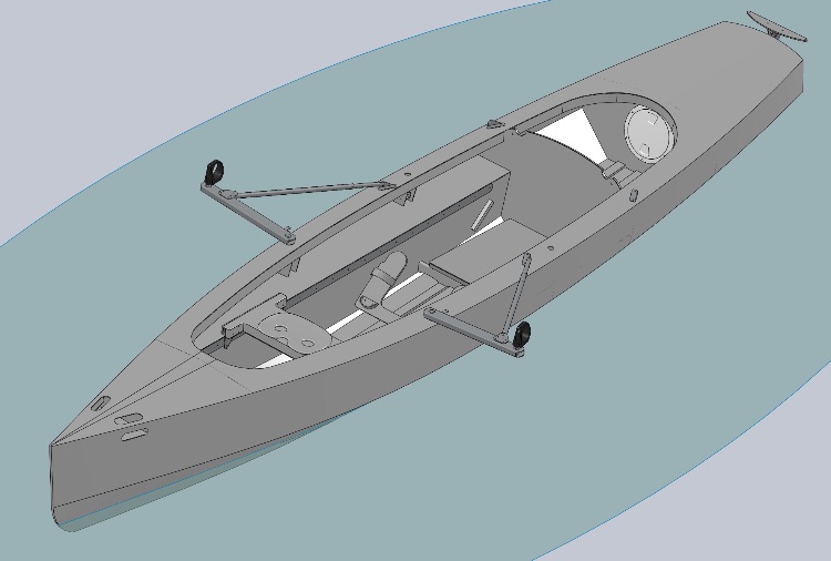 John, is this design of yours the one you are cutting? Illustration you posted of her last year on the Perfect River Raid Boat thread. Looking forward to seeing her built if it is this one. Any major changes? Brian |
|
|
Hi Brian - yes that's the same design but it has evolved since last year. Attached is a more recent picture with the rowlocks in the forward position as they would be for carrying a passenger. Most obvious change is a longer foredeck and shorter aft deck made possible by having a bit fuller underwater sections aft but there are also many detail changes. For anyone who is curious about it I attach the .dxf file for cutting the four and a bit sheets of plywood, also a .pdf version, as it stands at present. Comments welcome from those who know about this kind of thing. There are some rather strange shapes. For example the long thin shapes are to make up the stem timber/breasthook? from several layers of thin ply, you may have seen contour map models made that way. Perhaps not the strongest way but should be very easy to do if the shapes are feasible to cut - if they fall apart in the cutting I can make it some other way. I havent had time to research cutting methods much but from a couple of phone calls it seems that waterjet cutting may well be a better option than routing.
I had been planning to take the plywood to a water jet cutting company this afternoon but while we were at Coalport for the excellent presentation by Jeremy Warren at the DCA meeting on Sunday, Josephine asked me whether the new boat would have berths for both of us overnight. I had to tell her that it would not, and indeed I had not even considered that as a possibility. She seemed unhappy about that and since this is intended to be her boat this is a setback. 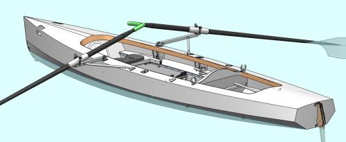 15-03-28_plywood_parts.pdf 15-03-28_all_sheets.dxf The boat as drawn and fitted with a hoop tent cover would actually offer the possibility of a comfy canvas berth for one person but to provide a double berth in the conventional way would mean starting right at the beginning again and would probably result in a much wider boat that would not really meet our other requirements. I have been wondering about having two berths end to end, the aft berth extending right to the transom, but at the moment I am not sure how practical this would really be with such a narrow boat, even though we would only be using it on inland waters or in very benign conditions on the sea. Even a small design change at this stage would set back the program such that there is no chance to have the boat ready for the Thames trip this year, but there will be future HBBR trips to take part in - at least I very much hope so. Making the drawings using a computer is actually a fairly rapid process, although by no means instant, but thinking about and mentally evaluating the countless possible design options is not a rapid process! |
|
|
Hi John "Making the drawings using a computer is actually a fairly rapid process, although by no means instant, " What software did you use to design it? Thanks On 30 Mar 2015 22:01, "John P [via UK HBBR Forum]" <[hidden email]> wrote:
Hi Brian - yes that's the same design but it has evolved since last year. Attached is a more recent picture with the rowlocks in the forward position as they would be for carrying a passenger. Most obvious change is a longer foredeck and shorter aft deck made possible by having a bit fuller underwater sections aft but there are also many detail changes. For anyone who is curious about it I attach the .dxf file for cutting the four and a bit sheets of plywood, also a .pdf version, as it stands at present. Comments welcome from those who know about this kind of thing. There are some rather strange shapes. For example the long thin shapes are to make up the stem timber/breasthook? from several layers of thin ply, you may have seen contour map models made that way. Perhaps not the strongest way but should be very easy to do if the shapes are feasible to cut - if they fall apart in the cutting I can make it some other way. I havent had time to research cutting methods much but from a couple of phone calls it seems that waterjet cutting may well be a better option than routing. |

|
|
Peter asked "What software did you use to design it?"
Well, I think I may have said here before that asking someone what software they used to design a boat is a bit like saying to an author "I liked that book you wrote, tell me, did you use a ballpoint or a fountain pen?" In this case it was Solidworks, but I am sure there are good alternatives. The other CAD software I have tried in recent years is 'Inventor' which would also be suitable. Solidworks may not be the ideal software if you want to do a lot of work with fancy curvy surfaces such as you do tend to have in boat and yacht design, or automobile design for that matter. I have heard that Catia (which shares its basic mathematical algorithms with SolidWorks) is one option that does complex surfaces better. Also, I understand that there is add on software available to extend the capability of SolidWorks for complex surfaces . However, I have found that the curved surface capability of the standard Solidworks software is quite adequate for the boat drawings I have done so far. However, getting the flat panel shapes from the curved surfaces is a bit of a fiddle with Solidworks. It would be nice if you could just click on a curved surface and select a 'flatten' option, I have heard that something like that is available with Rhino software. The way I have done it with SolidWorks is to pretend that the panel is made of sheet metal then use some of the functions in the sheet metalwork section of the SolidWorks software to flatten it. Its a bit of a fiddle to do it that way and I am not sure just how accurate it is, although I have cut out the panel shapes from thin cardboard at about 1:10 scale and as far as I can tell at that scale they do seem to fit OK. Solidworks, Catia, Inventor, Siemens NX and several of the other main CAD packages are described as 'parametric'. Its a bit difficult to explain in a sentence what that means, but basically the idea is that you dont describe geometry simply as measurements in mm or inches, instead you describe how the measurements of parts relate to each other. So, as a rather trivial example, suppose you are designing a boat that will be 12 feet long. You have to start somewhere, so it would be reasonable to begin by specifying the length as 12 feet. But then, when you come to the beam, you dont specify that in feet, rather you specify it as, say, a third of the length or perhaps as some more complicated function of dimensions that are already known in terms of other dimensions. You continue in that way with very little need to specify dimensions directly. That way everything in the design is related and when you need to alter one part there is at least a chance that all the other parts will automatically change to match in a sensible way which makes it much easier to see the effect of various changes to the design. My understanding, (and I am sure any Rhino users will rush to correct me if I am wrong) is that Rhino software is not parametric. I do find parametric software to be a big advantage so I havent considered Rhino myself, although I think it is used by many professional boat/yacht designers, indeed its probably true to say that it is used by the majority of professional yacht and boat designers. Anyway I digress. I am still wondering whether to start re-designing my project, or just go ahead and build it! |
|
|
In reply to this post by John P
John,
I have been following the development of your design ideas for the new boat with interest. I could not help a wry smile when I heard about your recent "setback", though. I hadn't realised this was destined to be Josephine's boat but perhaps I shouldn't be too surprised - every time I have seen the Grey Boat under oars, I think it has been your good lady who has been doing most of the hard work! I hope you resolve dilemma soon. Best regards, David. |
|
|
Hi,
A rowing boat made for two with sleeping space, we saw those on the Thames last year 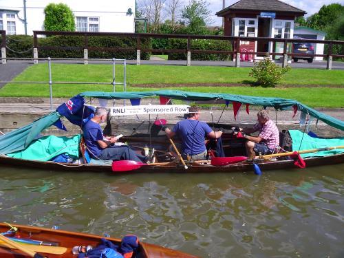 Didn't we? Steve 
|
|
|
In reply to this post by John P
On 31 Mar 2015 at 7:43, John P [via UK HBBR Forum] wrote:
> > I have heard that > Catia (which shares its basic mathematical algorithms with SolidWorks) > is one option that does complex surfaces better. Catia is not software that you could easily learn to use yourself. I used it professionally for a number of years and went on several months of courses and even then was only proficient with a subset of it's capabilities. If you want to model a complete helicopter, down to each nut, bolt and rivet then it is not too bad for the job. -- Sail when you can, row when you must, motor when you have to be at work in the morning. Alastair Law Yeovil, England. <http://www.little.jim.freeuk.com> |
|
|
A chap in the north east has been having some fun designing a 12' minimal touring canoe. His approach to software and useable output may be of interest. Note that building a half hull full size model is more common than one thought!
http://forum.woodenboat.com/showthread.php?188422-Minimalist-touring-canoe In summary this is the method: The process has been. ➡️ Develop the design in Delftship (free) ➡️ Export dxf file of the panels to Turbo CAD 12 (£30) ➡️ Save as pdf ➡️ Get pdf printed out full size ➡️ Paste paper templates to cheap exterior ply, cut out, stitch together with two frames So, Delftship is free and Turbo Cad was £30. Not too bad to have some fun, although I find Delft to hard to learn, too old and stupid. Brian |
|
|
In reply to this post by David Bewick
Hi Dave, good to meet up at both Semaine du Golfe (very briefly!) and also Beale Park. Thanks also for sending me the picture of our boat at SduG. Adapting my rowing boat design so that two persons could stay on board overnight would be a big design change and would probably mean some compromise to our original requirement for a simple boat for day trips on inland waters or from our local beach in calm weather. The project was put on hold for a few weeks, then we decided to go ahead and build the boat as originally designed. We would like to do more exploration of inland waters by oar power but we dont yet have enough experience of that kind of boating to really know how much of an advantage it would be to be able to stay on the boat overnight. If our new boat turns out to be not what we want it will be chopped up and another one designed and built! I took my plywood and dxf file to a firm with a water jet cutting machine early last week and I hope the cutting will be done within the next couple of weeks. This is all a bit of an experiment for me - I dont know how to optimise the dxf file for cutting or what are the capabilities of the process. The company took a quick look at my file and didn't seem to think there would be a problem. They said that when I came back there would just be a pile of bits - they would cut the parts out completely rather than leave them still partly attached to the rest of the sheets. Sounds good but will have to see how it all works out. In the meantime I have made most of the metal work for the boat including the aluminium folding rowlock outriggers. I have been keeping a note of the time that I am spending on the construction since that is something that people seem to ask home boat builders about. So far the metal work has taken me about 25 hours and it has been a pleasant enough job. People are also interested to know what home made boats cost. My guess is that this one will cost a bit under £1500 including buying a pair of racing style oars. I expect one could buy a second hand rowing boat for much less than that, but that's not the point is it. I think I could make a suitable pair of oars out of wood or even carbon fibre, but they probably wouldnt be quite as good as brought ones and the job does not particularly appeal. Would welcome any thoughts on oars for this style of boat. Looking on the internet 'Concept2' seems to be the one predominant brand. I notice that Fynne boat kits sell oars that look similar to the Concept2 ones. |
|
|
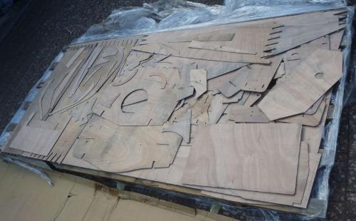 I have now taken delivery of the pre-cut plywood parts for my proposed rowing boat. They were cut using the waterjet process, a sufficiently high pressure jet of water will easily cut plywood, indeed it will cut almost all sheet materials, even hardened steel and suchlike. The parts were supplied wrapped in cling film on an 8 foot x 4 foot palet which I collected on my roof rack. The picture shows how it all looked when I unwrapped it - a big jigsaw puzzle. The waterjet cutting seems to produce very clean accurate cuts, I would not think that a router could do much better, if any better. With waterjet you can have sharp internal corners whereas with routing there will be a cutter radius at internal corners. I understand that plywood parts cut by routing are not usually fully separated from the rest of the sheet from which they were cut, whereas these parts were all supplied fully cut out which saves a little bit of work. On the other hand, a router can cut to variable depths, so that you could potentially have parts of varying thickness, whereas a water jet (or laser) can only cut out two dimensional shapes. You will see from the photo that the plywood has been slightly stained in places. My guess is that this is due to the water in the cutting machine being dirty from previous jobs. This staining would make the parts unsuitable if you wanted a clear wood grain finish, but it doesent matter to me since these parts will all be epoxy coated then painted. Perhaps if you do want a clear finish on your parts you could discuss this with the cutting firm, maybe they could avoid the staining by changing the water in their machine. I have trial fitted a few of the small parts and so far all looks good, perhaps the test will come when I get to fit the main hull pannels together. Very satisfying to see how perfectly the finger joints match up. I could never achieve such accuracy and such complicated shapes with manual cutting, but then again, if I had intended manual cutting I would not have designed the boat with so many weird shaped pieces of plywood in the first place. |
|
|
Almost instant boat! Except for the months of careful designing and the assembling...
Do like not having that endless marking up and cutting out with the considerable opportunities to introduce manual errors as you do so.
|

«
Return to Builds in Progress
|
1 view|%1 views
| Free forum by Nabble | Edit this page |